ATM is a circuit switched protocol. POS is a point-to-point technology, IP is packet switched, and Ethernet is a broadcast technology.
When a switch receives a frame with an unknown destination MAC address it floods the frame to all ports except the one the frame was received on. ICMP messages are used by routers rather than switches.
A router must be used to route the packets at the IP layer in order to facilitate communication accomplished between two users on separate VLANs.
TDM was initially developed for the PSTN reason.
The majority of ATM adaptation layer traffic today is AAL5, which is a simple, connection-less, non-real-time service data such as IP.
Application, Presentation, Session, Transport, Network, Data Link, and Physical are all valid an OSI layers.
A corrupted frame is typically detected in Ethernet by using the FCS field in the Layer 2 header.
The source MAC address is stored in the FDB along with the port the frame arrive on when a frame arrives at a port on an Ethernet switch.
The purpose of VLANs is to separate broadcast domains.
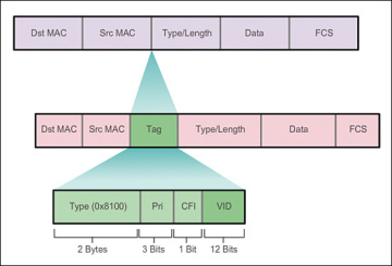
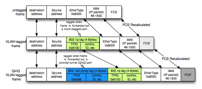
When VLANs need to span more than one switch, a VLAN tag is attached to the Ethernet frame to indicate VLAN membership. There is no per MAC address signaling done between switches.
The outer tag is commonly used by the service provider, and the inner tag is commonly used by the customer regarding the use of Ethernet Q-in-Q.
IP is encapsulated in PPP and transported over SONET regarding POS.
One of the reasons for ATM's fixed 53-byte cell size was to have a relatively small size to minimize delay and jitter for voice services. Another reason was to simplify high-speed switching requirements for optical networks.
Five service classes are defined by ATM. The different service classes are AAL1 (CBR), AAL2 (VBR-rt), AAL2 (VBR-nrt), AAL3/4 (ABR) and AAL5 (UBR).
IOMs are configured first, followed by MDAs, followed by ports regarding the required order for configuration of Alcatel-Lucent 7750 SR ports.
Display and examine the current card configuration with the show card command.
A:vRR# show card
===============================================================================
Card Summary
===============================================================================
Slot Provisioned Type Admin Operational Comments
Equipped Type (if different) State State
1 (not provisioned) up unprovisioned
iom3-xp-b
A sfm4-12 up up/active
B sfm4-12 up down/standby
(not equipped)
===============================================================================
A:vRR#
The example output given in the shows exactly two cards present. They can be easily identified physical cards in the chassis since they have a (not equipped) name in the "Equipped Type" column. Any card appearing Slot "A" or "B" is an SF/CPM card; the example shows only one in Slot A. The example shows one IOM card, of type iom3-xp-b.
The slots reserved for SF/CPM cards are always identified by a letter, either A or B.
IOM cards are referred to by the slot that they occupy in the chassis. Generally, there are either five or 10 slots for IOMs, so cards will have numeric labels from 1 to 10.
The first character in the prompt identifies which SF/CPM card is active, either Slot A or Slot B.
Configure the IOM card to the same type as Equipped. The specific card type may be different on the router.
A:vRR# configure card 1 card-type iom3-xp-b
Wait a few moments, and repeat the show card command to see the IOM in its final state
*A:vRR# show card
===============================================================================
Card Summary
===============================================================================
Slot Provisioned Type Admin Operational Comments
Equipped Type (if different) State State
1 iom3-xp-b up up
A sfm4-12 up up/active
B sfm4-12 up down/standby
(not equipped)
===============================================================================
*A:vRR#
Configuring an IOM card only changes the "Operational State" making a card available. It does not change the number of physical cards, as seen by the absence of any changes in the "Equipped Type" column.
The "*" reappeared to indicate an unsaved configuration change. Issuing the admin save command would make it disappear (until the next configuration change).
Have a look at the main log to see if anything has been recorded as a result of these last few configuration changes. Use the command show log log-id 99.
Display and examine the current MDA configuration using the show mda command.
*A:vRR# show mda
===============================================================================
MDA Summary
===============================================================================
Slot Mda Provisioned Type Admin Operational
Equipped Type (if different) State State
1 1 (not provisioned) up unprovisioned
m5-1gb-sfp-b
===============================================================================
*A:vRR#
Cannot see any MDAs for IOMs that are not configured. Unless an IOM has been configured, it is not possible to get any information about the MDAs that it contains.
In the example, the IOM only has a single MDA plugged into it. At most, two MDAs can fit into an IOM.
The MDA is plugged into the IOM in Slot 1. This is determined by the value in the Slot column in the command output. The MDA is plugged into the first of the two available MDA slots on the IOM. This is determined by the value in the Mda column in the command output.
Generally, an MDA will always be configured to be the same as shown in the Equipped Type column. Configure the available MDA(s). Note that the exact command will depend on the physical hardware; follow the rule of configuring the type to be the same as shown in the show command.
*A:vRR# configure card 1 mda 1 mda-type m5-1gb-sfp-b
*A:vRR#
In the command configure card 1 mda 1, the parameter card 1 identifies the IOM in Slot 1; the parameter mda 1 identifies the first of the two available MDA slots on the IOM card.
Display and examine all MDAs that are now visible.
*A:vRR# show mda
===============================================================================
MDA Summary
===============================================================================
Slot Mda Provisioned Type Admin Operational
Equipped Type (if different) State State
1 1 m5-1gb-sfp-b up up
===============================================================================
*A:vRR#
Configuring an MDA only changes the "Operational State" making an MDA available. It does not change the number of physical cards, as seen in" the absence of any changes in the Equipped Type column.
Have a look at the main log to see what has been recorded as a result of this configuration change.
*A:vRR# show log log-id 99
192.0.2.160 and 192.0.2.191 are not used as host addresses on the IP network 192.0.2.160 with a subnet mask of 255.255.255.224 because they are reserved as the subnet and broadcast addresses for the subnet.
Display and examine the current port configuration with show port command.
The first section is all the physical ports for the MDA(s) in IOM 1, as indicated by the section heading "Ports on Slot 1."
Ports on an MDA are named using three numeric values, for example, 1/1/5. The first value identifies the IOM, the second value identifies the MDA, and the third value identifies the actual port. The (management) ports on an SF/CPM card are named using two values - for example, A/1. The first value identifies the SF/CPM card, and the second value is always a "1" since there is only a single Ethernet port on each SF/CPM card.
By default, ports start in the Down state. This is an important point to remember since IOMs and MDAs automatically go to an Up state as soon as their type is configured.
The default MTUs for each type of port: 1514 for 10/100 FastE ports and 9212 for GigE ports.
Configure a single port to a functional state using configure port x/x/x no shutdown command.
SR - OS FundamentalsHigh Leverage Network (HLN)What is HLN?HLN = A platform for innovation
APPLICATION ENABLEMENT
CAPTIVATE YOUR CUSTOMERS
Leverage your assets to create personalized content and conversation experiences
Capture the creativity of open innovation
Develop new business models, increase ARPU, reduce churn
UNIVERSAL ACCESS
REACH MORE CUSTOMERS
Extend always-on broadband to everyone, everything, everywhere
Expand customer base, make high-speed broadband affordable
Enable open access, bridge fixed and mobile worlds
NETWORK EVOLUTION
LEVERAGE YOUR NETWORK
Evolve to a scalable, efficient and intelligent service delivery network
Leverage technical innovations in IP and optics
Enable new service value, manage capacity and scale at low cost
OPERATIONAL TRANSFORMATION
TRANSFORM YOUR OPERATIONS
Unify network, IT and business systems
Enhance service agility, reduce costs
Reduce OPEX, increase efficiency, enhance quality of experience
Tackle Today's Network ChallengesREALIZING THE POTENTIAL OF A CONNECTED WORLD
Revenue/subscriber
Increase revenue:
Leverage network intelligence
Deliver differentiated services
Develop new business models
Monetize assets
Cost/subscriber
Reduce costs:
Scale bandwidth dynamically
Manage capacity effectively
Transform operations efficiently
Harness technical innovation
IES Routed Connectivity Service Example
Since the traffic in an IES service communicates using an IP interface for the core routing instance, there is no need for the concept of tunneling traffic to a remote router
A basic IES does not require the configuration of any SDPs
configure service ies 1000 customer 1 create
description "IES training"
interface "to_CE" create
address 192.168.100.1/30
sap 1/2/8 create
exit
exit
no shutdown
There are two new pieces of information, both related to the physical cabling attached to the port. The Link column identifies whether cables are connected and attached to equipment at both ends, that is, Yes. The SFP/XFP/MDIMDX column identifies whether the cabling is connected as straight through (i.e., "MDI") or cross-over (i.e., "MDX").
Configure all ports Up that need or want to use. Configure the ports as a range, using a single command using configure port x/x/[2..10] no shutdown command.
Configure the system IP address of a router using configure router interface "system" address x.x.x.x/32 command. Verify by show router interface command.
The system interface is present by default.
The system interface cannot be removed.
The system interface admin status is up before and after an IP address is assigned. It can, however, be explicitly shut down.
The operational status of the system interface is down before an IP address is assigned. The operational status of the system interface will change to up after an IP address is assigned as long as the admin status of the system interface is also up.
A physical port cannot be assigned to the system interface. The system interface is similar to a loopback interface because its operational status is not affected by the state of any particular port. This makes the system address ideal for communication with other devices.
Avoids fluctuation of traffic/LSPs in the event of a flapping link or a link with a high error rate. configure port Ethernet hold-time up 50 (second)
Auto-negotiation should be disabled on Ethernet or Gigabit Ethernet links that are physical members of an 802.3ad Link Aggregation Group (LAG). configure port ethernet no autonegotiate
The maximal MTU value available to services will be lower than the physical (or port) MTU value, due to MPLS encapsulation overhead when transporting user frames/packets over the network. configure port ethernet mtu 9212
Enabling dynamic costing causes the physical link metrics used by IGP to be applied based on the operational or aggregate link bandwidth in the LAG that is available at the time. configure lag dynamic-cost
Multi Chassis LAG (MC-LAG):
On AC-1 and AC-2, identical LAG configuration will be applied. configure
lag
description
mode access
port priority
lacp
no shutdown
exit
On CE, following configuration will be applied. configure redundancy
multi-chassis
peer create
mc-lag
lag lacp-key system-id system-priority
no shutdown
exit
no shutdown
exit
exit
The IEEE 802.1ab Link Layer Discovery Protocol (LLDP) standard defines protocol and management elements that are suitable for advertising information to stations attached to the same LAN for the purpose of populating physical or logical topology and device discovery management information database. configure port
ethernet
lldp
dest-mac nearest-bridge
admin-status tx-rx
notification
tx-tlvs port-desc sys-name sys-desc sys-cap < port description, system name, system descriptions and system capabilities
tx-mgmt-address system
exit
exit
Configure the router interfaces required for the point-to-point links. Point-to-point links generally use /30 subnet marks for efficient use of IP address space. configure router interface toR5
address x.x.x.x/30
port 1/1/4
When a router interface is created, the default admin state is up regardless of any IP address configuration.
If a router interface is created and an IP address is assigned but no other actions are taken, the operational status will be down.
The router interface used on the physical links are not loopback or system interfaces. Therefore, a physical port must be bound to the interface to bring it operationally up. Note that the physical state of the port will also affect the state of the router interface.
The principle of IS-IS management model is divided into 2 levels (two level hierarchies). If domain is large may be divided into small management area. Level 1 routing is to find path within area. Level 2 routing is to find path between areas.
At L2 router can optimize IGP to reduce the number of SPF calculation by configure ISIS multiple instance and performing route summarization.
In IS-IS, if the metric is not configured, a default cost of 10 is used. Originally, the maximum metric for a link was limited to 63 (6 bits), with a total path metric of 1023 (10 bits). These limits were not considered granular enough for modern networks, especially with traffic engineering, so a new "wide metric" was defined. The wide metric uses 24 bits to support a link metric of 16,777,215 and a total path metric of 4,261,412,864. A path that has a greater cost than the limit is considered unreachable.
On point-to-point adjacencies, the election of a Designated Intermediate System (DIS) and regular generation of CNSPs is an unnecessary function. configure router isis
interface
interface-type point-to-point
Configure interface into IS-IS area 49.01 as a Layer 2 point-to-point interface. configure router isis
area-id 49.01
level-capability level-2
interface "toR2" interface-type point-to-point Verify by show router isis adjacency and show router route-table protocol isis
Verify LSPs database by show router isis database and show router isis database .00-00 detail Because router has been configured as an L2 only router, there are no L1 LSPs in IS-IS database. There is one L2 LSP in the IS-IS database that includes the network of interface toR2.
Note that the L2 LSP is created even though there are no IS-IS adjacencies on which to send the LSP to other routers.
Advertise the system interface into IS-IS configure router isis interface "system"
If passive interface is configured, all same Level IS-IS routers will aware of it and have a corresponding route in their route tables.
Configure MD5 authentication type configure router isis
authentication-type message-digest
authentication-key The advantage of MD5 authentication is that the authentication keys are encrypted rather than sent in plaintext.
Configure the router to use wide metrics and a reference bandwidth so that IS-IS computes link metrics the same way as OSPF. configure router isis
reference-bandwidth 10000000
level 2 wide-metrics-only
Multiple IS-IS areas can be used to improve scalability and convergence time.
An L1 adjacency will not form in different areas. They must be L2-capable to form an adjacency with a router in a different area.
Configure router to summarise address configure router isis summary-address level-2
RFC 5130 defines the ability to add an additional attribute to IS-IS routes - the administrative route tag. This can be used to identify certain routes that are to receive some special treatment at another point in the network. This might be for routes that are to be exported to another protocol such as BGP (Border Gateway Protocol) or to control leaking between levels in IS-IS.
Bidirectional Forwarding Detection (BFD) offers a light-weight, low-overhead, short-duration detection of failures in the path between two systems. configure router isis
interface
bfd-enable ipv4
Transport Tunnels and Service Tunnels:
MPLS or GRE tunnels are used to transmit customer data across the service provider network
Multiple service tunnels can be carried within a transport tunnel
Multiple transport tunnels can be configured on a single network port
Inner service label defines the service tunnel; outer transport label defines the transport tunnel
Transport and Service Label Encapsulation:
MPLS encapsulation of VPN service traffic:
DLC header - Layer 2 header used to transport the MPLS packet
MPLS transport (outer) / tunnel label - The label signalled by the next-hop PE
Service (inner) label - The service, or virtual circuit (VC) label that identifies the service the packet belongs to
Control word - Optional and primarily used for ATM or Frame Relay services
Service packet - The customer data being transported by the service
GRE encapsulation of VPN service traffic:
IP header and the GRE header are used instead of the MPLS transport label
A service label is still required to demultiplex the packet to the appropriate service
The service provider routers use the GRE header to route the packet across the network
MPLS transport tunnel signalling protocols:
LDP or RSVP-TE are used to set up LSPs
Provide a means to set up label-switched paths, also known as LSPs, that can carry many other service tunnels
Service tunnel signalling protocols:
Service labels, or VC labels, are used to encapsulate and identify customer traffic that belongs to a particular service
A service label is applied to the customer traffic before the transport label, or LSP label is applied
VPLS and VPWS services are signalled using targeted LDP, also known as T-LDP
VPRN service is signalled by MP-BGP, based on RFC 4364 (formerly RFC 2547bis)
Service Label Signalling:
An IGP is used to provide IP reachability to the routers
LDP or RSVP-TE is used to signal the transport tunnel label. Once LDP/RSVP-TE converges end-to-end, an LSP is created
T-LDP or MP-BGP is used for service signalling. This provides the inner/service label
The exchange of service labels occurs when the pseudowire is created
The following outlines the service label signalling process:
PE2 sends PE1 a service label (11350)
PE1 sends PE2 a service label (21350)
Unidirectional service tunnels are created
PE1 uses the label (11350) to send traffic towards PE2
Likewise, PE2 uses label (21350) to send traffic towards PE1
Distributed Service:
A distributed service has components on multiple routers and uses the IP/MPLS network to connect the service and deliver data
SDP binding is required to signal the service labels and define the transport to the remote router
Binding an SDP to a Service:
SDPs provide the binding between the control plane signalling of service labels and the transport tunnels (LDP/RSVP or GRE)
To direct a service to use an SDP for distribution, the service is joined to the SDP using SDP binding
A service label is not signalled unless the service is bound to an SDP
Because all service distribution relies on the SDP, the transport is most often RSVP with fast rerouting capabilities
Distributed Service Configuration:
The following steps must be completed for a successful distributed service operation:
IGP configuration - ensure that routing tables have system addresses
Signalling transport labels are enabled for either LDP or RSVP
LDP has to be enabled for dynamic signalling of service labels using T-LDP
Creation of a path - if using RSVP
Creation of LSP and bind path - if using RSVP
Creation and binding of SDP to LSP - if using RSVP or select LDP
Service Verification:
Once the service is configured on the remote router with a matching VC ID, a service label is signalled and the service is up:
PE# show service id 50 base Provides a summary status of all services
A service label is signalled and the CE routers can connect to each other through the epipe:
PE# show router ldp binding fec-type services
CE# ping 192.168.2.2 size 1472 do-not-fragment count 2
An example of SDP Path and Network Port MTU:
For a gigabit Ethernet network port with an MTU of 9212 (default on the 7750 SR)
If SDP uses MPLS encapsulation:
SDP path MTU = 9212 (network port MTU) - 14 (Ethernet header) - 8 (two MPLS labels) = 9190 bytes
The MPLS/VPRN control plane consists of routing information and label exchange
Distinct sets of routes must be exchanged
Provider core routing
Customer VPRN routing
Distinct sets of labels must be exchanged
VPN service labels
VPN Service Labels via MP-BGP:
Inner MPLS (VPN) label is included in the MP-BGP update
Tells the far-end PE which label push on the stack such that VPRN data is encapsulated to the correct VRF
6VPE Data Plane - Ingress 6VPE Router:
When the ingress 6VPE router receives an IPv6 packet, it looks for the destination address in the VRF table
This destination prefix is either local to the 6VPE (which is another interface participating in the VPN) or a remote ingress 6VPE router
For the prefix learned through the remote 6VPE router, the ingress router does a lookup in the VPN-IPv6 forwarding table
The VPN-IPv6 route has an associated MPLS label to an MBGP next-hop and an associated VPRN service label
The ingress 6VPE router needs to push two MPLS labels in order to send the packets to the egress 6VPE router
The top label is an MPLS IPv4 label that is used to reach the egress 6VPE router
The bottom label is an MPLS label that is advertised in MBGP by the remote 6VPE router for the IPv6 prefixes in the VRF
6VPE Data Plane - Egress 6VPE Router:
The provider core (P) routers label switch the packets to the correct egress 6VPE via the transport label
The egress 6VPE router receives label-stacked packets from the core
The egress 6VPE router pops the top transport label
The egress 6VPE router pops the bottom IPv6 VPRN service label and identifies the target VRF and the address family
A further Layer 3 lookup is performed in the target VRF and the IPv6 packet is sent toward the proper customer edge router in the IPv6 domain
The egress 6VPE forwards unlabeled packets to the customer
Types of VPWS:
Epipe - emulates a point-to-point Ethernet service
Apipe - emulates a point-to-point ATM service
Fpipe - emulates a point-to-point Frame Relay circuit
Cpipe - emulates a point-to-point TDM circuit
Ipipe - provides IP interworking capabilities between different Layer 2 technologies
Service Configuration:
Once the service infrastructure has been configured, the distributed service can be provisioned
The configuration of an epipe is shown below:
# configure service customer 100 create
>config>service>cust$ exit
# configure service epipe 50 customer 100 create >config>service>epipe$ sap 1/1/3:50 create
>config>service>epipe>sap$ back
>config>service>epipe# spoke-sdp 2:50 create
>config>service>epipe>spoke-sdp$ back >config>service>epipe# no shutdown
>config>service# epipe 50 customer 100 create service-mtu 1518
sap 1/1/4:50 create
exit
spoke-sdp 2:50 create
exit
no shutdown
exit
# show service id 50 base
Local epipe service configuration on a single router:
# configure service epipe 50 customer 100 create
>config>service>epipe# sap 1/1/1 create
>config>service>epipe>sap$ exit
>config>service>epipe# sap 1/1/2 create
>config>service>epipe>sap$ exit
No SDP need to be created
Distributed Service Configuration - Continued:
Customer-facing ports must be changed to access mode and encapsulation must be changed as required to any of the following: null, dot1Q or q-in-q
Creation of the service and selection of the service type, including any of the following: epipe, fpipe, apipe, ipipe or cpipe. In addition, the following must also be done:
Add SAPs to service
Add SDPs to service with VC ID
Epipe service does not perform any MAC learning
Epipe SAP Encapsulation:
SAP encapsulation provides the router with a way of delineating services
Ethernet encapsulation:
Null - supports a single service on a port
No VLAN tag
Example - Port 1/1/1
Service is delimited by the port (SAP 1/1/1)
The physical port belongs to a single service and a single customer
Tags are treated as customer data and are transparent on the network
Dot1Q(802.1q) - supports multiple services for a single customer or multiple services for multiple customers
1 VLAN tag
Example - port 1/1/1:10
Service is delimited by the VLAN tag (SAP 1/1/1:10)
Allows more than one SAP to be configured on each physical port
Q-in-Q - provides a way to differentiate between customer services based on Q-tags
2 VLAN tags
Example - port 1/1/1:10.100
Service is delimited by two VLAN tags as portuter.inter (SAP 1/1/1:10.100)
Can specify a top and bottom VLAN ID to be matched
VLAN tag is used to determine which service the frame belongs to
Multiple SAPs can be defined on a single port for different services
Ethernet Frame Encapsulation in an Epipe Service:
On the 7750 SR, VLAN tags are stripped at the SAP ingress by default
If ADSPEC is configured on the LSP used as the transport for the SDP, the SDP path-MTU is derived from the path MTU signalled in RSVP using the ADSPEC object
Negotiated MTU for the LSP is set to the smallest MTU value found on the path
configure router mpls
lsp "to-PE2"
to 10.10.10.2 adspec
primary "loose" exit
no shutdown
show router mpls lsp "to-PE2"path detail
The SDP path MTU: show service sdp 2
The service will down if the SDP path-MTU less than the service MTU
show service id 50 sdp 2:50 detail
Verification:
The command show service id 50 all displays detailed information related to all aspects of the service
SDP and VC Type:
RFC 4448 defines two VC types for the Ethernet pseudowire
The VC type is specified when the SDP is bound to the service and is signalled by T-LDP
Ether - specifies raw mode (default)
The service delimiting VLAN tag is stripped at the ingress and is not carried across the epipe
VLAN - specifies tagged mode
A VLAN tags is carried in the frame
VC Type Configuration:
The epipe which is configured with type VLAN: configure service epipe 50 service-mtu 9000 sap 1/1/4:50 create
exit
spoke-sdp 2:50 vc-type vlan create
vlan-vc-tag 150
exit
no shutdown
The epipe which is using type Ether: configure service epipe 50 service-mtu 9000 sap 1/1/4:50 create
exit
spoke-sdp 1:50 create
exit
no shutdown
T-LDP will not make a pseudowire operational unless the VC ID and VC type match show service service-using epipe
Change type Ether to VLAN: configure service epipe 50 spoke-sdp 1:50 shutdown
spoke-sdp 1:50 vc-type vlan create
vlan-vc-tag 150 no shutdown
exit
Fpipe Common Configuration Tasks:
The fpipe uses the same provisioning steps as an epipe, with the following exceptions:
The service type is fpipe
The physical port or channel is a SONET port set for Frame Relay framing
SAP is in the form of portLCI (example - 1/1/1:65)
The Interworking VPWS capabilities are:
ATM:
ATM: Apipe
Frame Relay: Apipe (FRF.5 interworking)
Ethernet: Epipe (bridged) / Ipipe (routed)
Frame Relay:
Frame Relay: Fpipe
Ethernet: Epipe (bridged) / Ipipe (routed)
Ethernet:
Ethernet: Epipe
An ethernet VPN service, such as an epipe service, has a default service MTU of 1514 bytes
Spoke SDP Termination on VPWS:
Connect a spoke SDP of a VPLS service (mesh-sdp) with an epipe service (spoke-sdp)
The VC-ID of the spoke SDPs on the epipe service and the VPLS service must match
VC-ID does not have to match the service ID of either the epipe or the VPLS
The service MTU of the VPLS and epipe service must match
Configuration: configure service vpls 1000 stp
shutdown
exit
sap 1/1/4 create
exit
spoke-sdp 1:100 create
exit
mesh-sdp 3:1000 create
exit
mesh-sdp 4:1000 create
exit
no shutdown
The example of svc-ping: oam svc-ping 10.10.10.4 service 100 local-sdp
oam svc-ping10.10.10.4 service 100 local-sdp remote-sdp
The svc-ping output shows the service MTU as the configured value for the epipe
The example of Local Mirror Configuration:
The mirror destination is configured on SAP 1/1/2
The mirror source is configured on SAP 1/1/4 of the epipe to mirror both ingress and egress traffic
configure mirror mirror-dest 99 sap 1/1/2 create
exit
no shutdown
debug mirror-source 99 sap 1/1/4 ingress egress
no shutdown
exit
Create a sniffer using IP filter on an epipe SAP configuration:
It looks as if all sites appear to be connected to a single-switched VLAN
Transparent to the customer's data
Can operate over a single, local site or over multiple, geographically-dispersed sites
Fames are only forwarded across the required links in the network
Service provider's perspective:
The advantages to the service provider are similar to those of a VPWS service
VPRN Advantages:
Customer's perspective:
Sites are connected to a private routed network administered by the service provider for that customer only
Separate and independent IP address plan per VPRN
The VPRN can operate over a single local site or over multiple geographically-dispersed sites
Service provider's perspective:
The advantages to the service provider are the same advantages as for a VPWS or VPLS service
VPLS Overview:
VPLS is an Ethernet service that connects multiple sites in a single switched domain over the provider-managed IP/MPLS network
VPLS is essentially an enhancement of the VPWS
Multiple VPLS services can be deployed using the same IP/MPLS core
VPLS: Customer Operation:
Customers maintain complete control over routing
Adding new sites requires minimal reconfiguration at existing sites
Virtual Switch (VS) Functionality:
VPLS connects the customer's multiple locations like a virtual Ethernet switch
All SAPs belong to the same broadcast domain in a VPLS, regardless of the VLAN tags
VPLS Flooding Behaviour:
Known unicast traffic is sent to the destination
Traffic to multicast, broadcast or unknown unicast addresses is flooded to all local SAPs and remote PEs in the service
In a basic VPLS, the SDP is bound to the service as a mesh SDP
Mesh SDP floods frames received from a SAP or from a spoke SDP but does not flood frames received from another mesh SDP
Mesh SDPs prevent loops
Spoke SDP floods frames received from a SAP, spoke SDP or mesh SDP
On a dot1Q encapsulated port, frames with a VLAN tag of 0 and untagged frames are forwarded to the null SAP
By default, a PE Maintain a different Forwarding Data Base for each service and Mac learning to support VPLS services for different customers
Like any IP interface, the customer can use the IES interface as a neighbour for a routing protocol such as OSPF, IS-IS or BGP
A CE 6VPE deployment using a VPRN: configure router bgp
local-as 64497 group "group"
family ipv6
neighbor 2001B8:11::1 export "direct-bgp"
peer-as 64496 exit
exit
no shutdown
Epipe services do not consume any MAC resources because MAC learning is disabled
A VLAN tag of 0 is added as the provider VLAN tag when a packet without a VLAN tag is received on a SAP provisioned with null encapsulation while an SDP vc-type is provisioned as vlan
SDP path MTU:
The network port MTU between P is required to support a service MTU
To determine the effective path MTU of the SDP, the command oam sdp-mtu is used oam sdp-mtu 2 size-inc 1450 1500 step 10
The effective path MTU for SDP is the link MTU - 22 bytes transport encapsulation overhead
Fragmentation is not supported on a Layer 2 service
config>service# epipe service-id no shutdown commands is used to enable an Epipe service
config>service>ies# interface "to-CE" create command syntax would be used to create a new routed interface on an existing IES service
A separate MAC FDB is used on the PE for each VPLS service
6VPE:
6VPE does not require an IPv6-aware MPLS core
6VPE is a tunnelling technology that makes use of MPLS tunnels to transport IPv6 information over an IPv4 MPLS infrastructure
On the PE router, the next hop for a VPN IPv6 address is an IPv6 address, regardless of the nature of the network between the PEs
Customers connected to 6VPE could run native IPv6 or IPv4
VPRN:
Each VPRN consists of a set of customer sites connected to one or more PE routers
Each customer router becomes a routing peer of the provider router that is directly connected to, not a peer to the other customer routers
VPRN is an IP service that connects multiple sites in a single routed domain over the provider-managed IP/MPLS network
VPRN provides customer routers with transparent IP connectivity without knowledge of the MPLS core
The show routerfib command can be used to verify the contents of the FIB
Prefixes learned from traditional routing mechanisms are listed and associated with the traditional IP forwarding parameters of the next-hop address and egress interface
Prefixes learned from MP-BGP as VPN-IPv4 routes are listed and associated with the egress label and MPLS forwarding and LSP parameters
The basic idea behind lsp-ping and lsp-trace tests is to verify that packets that belong to a particular FEC actually end their MPLS path on an LSR that is an egress for that FEC
# oam lsp-ping prefix 10.10.10.4/32
The test fails if the LSP is not operationally up
Echo reply packets may not take the same path as the LSP
An echo request is sent based on the LSP's label stack
# oam lsp-trace prefix 10.10.10.4/32 detail
configure service epipe service-id customer customer-id create command is used to create a new Epipe service
The default 7750 SR behaviour describes all routes in a VRF that are advertised to other PE routers, does not advertise all routes in the VRF to a CE router
C-pipe service type would be used to provide a bi-directional Layer 2 connection of TDM circuits over an IP/MPLS network
The router reads the source MAC address of frames passing through the service describes how a MAC FDB is populated in a VPLS service
On a Nokia 7750 SR, by default, T-LDP is used for signalling service labels, the VC ID on the mesh SDPs of a VPLS are set to the service ID, and Mesh SDPs are used for VPLSes to avoid loops
Example of Remote Mirror Configuration - Mirror Source:
PE2# configure mirror mirror-dest [999] create
spoke-sdp 1:999 create
exit
no shutdown
exit
# debug mirror-source [999] sap 1/1/4 egress ingress no shutdown
exit
Mirror Destination:
PE1>config>mirror# mirror-dest [999] create
remote-source
far-end 10.10.10.2 exit
sap 1/1/2 create
exit
no shutdown
PE2# show service sdp-using
lsp lsp-name and ldp are used to configure an MPLS signalling type to be used on an SDP
sdp-ping:
Tests ability to reach the far-end IP address of an SDP ID within the SDP encapsulation
A data packet arrives at the ingress PE and is encapsulated with both the outer/transport label, learned through LDP, as well as the service label, learned through T-LDP or MP-BGP
As the data packet traverses the P routers, the outer label is swapped while the inner label remains unchanged
Upon receiving the data packet, the receiving/egress PE removes the outer LDP label. Then, prior to removing the inner label, the receiving PE maps it to the appropriate service
The result is the original data packet, which is then forwarded to correct interface for the service, and then on to the CE
The two PEs are providing 6VPE and IPv4 VPRNs. The core network is IPv4/MPLS. family vpn-ipv4 vpn-ipv6 is the BGP family configuration for the MP-BGP on the PEs
Traffic is flooded to all SAPs, spoke SDPs, and mesh SDPs in the service describes the flooding of traffic on a PE when traffic is received on a spoke SDP
FRF.5 is a standard that describes Frame Relay tunnelling over an ATM core network
VPRN Architecture:
Label Stack:
A VPRN service uses a label stack consisting of two labels
Layer 2 | LSP Label | VPN Label | IP Data
The outer label is known as the top, transport or LSP label and identifies the transport tunnel between PEs
Allows traffic to transit across the MPLS network
The inner label is known as the service or VPN label and identifies the customer VPRN service
MP-BGP is used to signal
Only the IP packet that is encapsulated for transmission across the VPRN
A Cpipe supports both structured and unstructured frames
Maximum Transmission Unit (MTU):
MTU is an important issue in both Layer 2 and Layer 3 services
For an IP/MPLS network, the following MTU entities must be considered:
Access port, or SAP MTU
Service and VC MTU
SDP path MTU
Network port MTU
Oversized frames arriving at a Layer 2 interface are not fragmented
Layer 3 services will fragment oversized packets for transmission
sap 1/1/1:4.* defines a SAP that will select frames with an outer tag of '4' and ignore any inner tag on a Q-in-Q encapsulated port
OAM tools are useful in managing and troubleshooting a network
MPLS paths diagnostic tools:
lsp-ping and lsp-trace
SDP diagnostic tools:
sdp-ping and sdp-mtu
Service diagnostic tools:
svc-ping
SVC-ping or Service ping:
Verify the round-trip/end-to-end connectivity and delay to the far-end of the service and test the SDPs of a service in both directions
Verify the correct and consistent provisioning of a service between two service end points
Service Distribution Point (SDP) Characteristics:
A service distribution point (SDP) is a logical entity used to direct traffic for a service from one router to another through a unidirectional service tunnel
SDPs are locally unique; the same SDP ID can be used on another router
SDPs use the system IP address to identify far-end destination
An SDP is not specific to one service; many services can use the same SDP
All services bound to the same SDP will have the same transport encapsulation
Any operations on an SDP will affect all services that are bound to that SDP
Configuring the physical port in access mode and Enabling the port using the no shutdown command need to be configured before a SAP appears
Set the ip-mtu of the IES to match the service MTU of the VPLS is the recommended approach for making sure that MTUs between a VPLS and its spoke IES termination match
PE1 and PE2 are providing a VPRN for the CEs. The traceroute run on CE1 will only show 3 hops: CE1-PE1, PE1-PE2 and PE2-CE2
A routing policy is not required on PE1 to advertise a CE1's system interface to PE2; the default behaviour on the 7750 SR is to advertise all VPRN routes between PE routers
IES Spoke SDP Termination to a VPLS - IP MTU:
The MTU values can be made to match by:
Changing the VC-MTU of the IES using the ip-mtu command (preferred method)
For Layer 3 service: the signalled VC-MTU = configured IP-MTU
A: PE-1# configure service ies 100 interface "To_VPLS_1000" ip-mtu 1500
Adjusting the SDP path MTU (not recommended)
Adjusting the network port MTU (not recommended)
Whereas in epipe and VPLS services the signalled VC-MTU = configured service-mtu - 14 (Ethernet header)
If the router is rebooted after an "admin save" has been performed, Only the mirror source must be re-configured
A network consists of four PE routers. A customer requires a VPLS and has sites connected to each PE. The VPLS is fully meshed using IP/MPLS. 3 SDPs must be configured on each PE
Hierarchical VPLS (H-VPLS):
Enables VPLS services to span multiple metro networks
Creates scalable VPLS. They allow a VPLS to scale more easily. They simplify the configuration required when adding new PEs
A spoke SDP is used to connect smaller meshed VPLSs together
The purpose of an MP-BGP in a VPRN:
The service provider uses MP-BGP to distribute the routes for the different customer networks
In a VPRN service, MP-BGP is used to exchange customer routes across the VPRN
Targeted (targeted) LDP/T-LDP or MP-BGP is used to establish/creates an end-to-end connection-oriented session between PEs, and providing/propagates the inner/service label
Transport tunnels:
RSVP-TE or LDP signalled LSP:
Labels are signalled using RSVP-TE or LDP
The MPLS-encapsulated data is forwarded to the egress PE for the service
GRE tunnel:
The data is encapsulated with an IP header
The source IP address is the ingress PE router and the destination address is the egress PE router
Typically used when there are routers in the transport network that do not support MPLS label switching
Service tunnels:
MP-BGP or T-LDP are used to set up per-VPN service tunnels
Multiprotocol BGP (MP-BGP):
Multiprotocol BGP (MP-BGP) extensions allow VPN-IPv4 prefixes to distribute VPRN routing information across the service provider's network
The VPN-IPv4 address family is only used in the provider core control plane when exchanging MP-BGP routing updates
Virtual Private Routed Network (VPRN):
VPRN is an IP (Layer 3) service that connects multiple sites in a single routed domain over the provider-managed IP/MPLS network
The VC-MTU is derived from the configured service MTU (VC-MTU = configured service MTU - 14 (Ethernet overhead, FCS not counted)
Service MTU cannot be configured on IES or VPRN service
If no service MTU is configured, the VC-MTU is derived from the configured SDP path MTU (VC-MTU = configured SDP path MTU - 14 (Ethernet overhead, FCS not counted)
If the SDP path MTU is not configured, the SDP path MTU and the VC-MTU are derived from the network port MTU
SDP path MTU = network port MTU - 4 (transport label) - 4 (VC-label) - port encapsulation (14 in case of null encapsulation, 18 in case of dot1Q...)
VC-MTU = network port MTU - 14 (port encap) - 4 (transport label) - 4 (VC-label) - 14 Ethernet overhead
VPRN Features:
VPRN site additions or removals can be accomplished with minimal additional configuration
VPRN utilizes MPLS label stacking:
The outer label allows traffic to transit across the MPLS network
The inner label determines the VPRN
Provides connectivity among any number of customer sites
Provides customer routers with transparent IP connectivity without knowledge of the core router
Enable MPLS:
Network ports and system interfaces are added to MPLS
Enable RSVP with the no shutdown command
A: PE-1# configure router mpls
interface "system"
back
interface "to-PE2"
back
no shutdown
configure router rsvp no shutdown
show router mpls interface
SDP Encapsulation Types:
MPLS encapsulation:
Uses LDP or RSVP-TE for label signalling
LDP relies on an IGP to find its path
RSVP-TE requires additional configuration
RSVP-TE allows finer control paths
GRE encapsulation:
Encapsulates traffic in an IP/GRE header, appears as an IP packet
Low control plane overhead
GRE uses normal IP routing to find a path
Multiprotocol BGP (MP-BGP):
The sending PE will add the RD to the IPv4 prefixes before sending the VPN-IPv4 prefixes in MP-BGP updates
MP-BGP updates include VPN-IPv4 unique addressing for customer routes and the RT to identify VPRN membership at the receiving PE
The route target identifies to the receiving PE the VRF that a VPN-IPv4 prefix is associated with
MP-BGP is an enhanced version of BGP that can carry customer route prefixes for multiple VPRNs
Signalling is required between the PE routers in order to provide the necessary connectivity information throughout the VPN. Two approaches exist to provide this end-to-end signalling information.
The Draft-Martini uses T-LDP between the PE routers to distribute VC labels. This mechanism contains information such as the unique VC ID, the specific interface parameters and the VC Type, such as ATM, Frame Relay and Ethernet. The PE routers use this information to build the forwarding tables and set up the VC LSPs.
The Draft-Kompella approach makes use of BGP between the PE routers to advertise route distinguishers and route targets. This enables the receiving PE to determine if the incoming BGP update is relevant for its VPN clients. If so, the receiving PE accepts the update and populates the forwarding tables accordingly.
Martini draft was standardized under RFC 4096. Draft-Kompella is obsolete and was not standardized
Service Access Point (SAP):
A SAP is the subscriber's point of interface/entry to the service network
A SAP is specified as a physical port and an encapsulation identifier
To be used as a SAP, a port must/can only be configured/created on a port configured as "access"
A SAP is created by specifying a physical port and an encapsulation type
SAP Configuration Considerations:
A SAP ID is locally unique - the same SAP ID value can be used on another service router
A SAP is associated with a single service and can only be configured on an access port
A port or channel can have more than one SAP configured on it
All SAPs must be explicitly created and are administratively enabled at the time of creation - there are no default SAPs
VLAN IDs have local port significance
A SAP can be configured with any of the following:
Ingress and egress filter policy
Ingress and egress QoS policy
Ingress and egress scheduler policy
Accounting policy
SAPs can be defined on Ethernet, POS, SONET/SDH, or TDM channels
Multiple SAPs can be defined on the same port
An Internet Enhanced Service is a routed service where the CE communicates with a Layer 3 interface to send and receive traffic
SDP IDs are locally unique and SDPs are a logical way to direct traffic from one router to another
VPN labels:
They are signalled between PE devices using MP-BGP
They are also known as the inner label or service label
They indicate to the egress PE the VPRN to which a packet belongs
An E-pipe is configured with a service MTU of 5000. 5004 is the minimum MTU value that should be set on an access port for a dot1q encapsulated SAP on this service
An E-pipe service configured with SAP 1/1/1:5 and SAP 1/1/1:6. If the SAP 1/1/1:5 accepts an ingress frame, the frame egresses from 1/1/1:6 with VLAN tag 6
In a VPLS service, the mesh-sdp vc-id is identical to the service id by default
A CE is connected to an IES interface must be on the same subnet as the IES
When configuring an IES spoke termination to a VPLS, Spoke-SDP with matching vc-id configured and MTU must match on both services must be explicitly configured in order for the service to come up
Must be configured when configuring an Epipe service:
Binding to an SDP if it is a distributed service
Enabling the service using the no shutdown command
Defining a SAP or SAPs
Configuring an Epipe service with a customer ID
Fpipe is a VPWS service would be used to create a point-to-point Frame Relay service
A VPLS receives a frame with the single VLAN tag 35 on the Q-in-Q SAP 1/1/1:35.*. Default behaviour is the VLAN tag is removed, and the frame is transported over the network
1540 is the minimum Ethernet physical network MTU required for a Layer 2 service on an MPLS encapsulated SDP with a service MTU of 1518
Tree config>service# in the CLI would need to be in to add a QoS policy to a SAP
The oam vprn-ping command is used to verify that the customer VPRN service is operational
PE1> oam vprn-pingsourcedestination
When a Router is rebooted the mirror source must be re-configured and a mirror destination is shut down by default
Complete the VPRN service configuration on PE for Customer Blue:
A: PE# configure service vprn 10 customer 10 create
description "Customer Blue"
router-id 10.10.10.1 autonomous-system 64496
route-distinguisher 64496:1 auto-bind ldp
vrf-target target:64496:10 interface "toR3" create
address 10.1.3.1/27 sap 1/1/3 create
exit
exit
bgp
group "toCE1"
neighbor 10.1.3.3 export "mbgp-bgp"
peer-as 64497
exit
exit
exit
no shutdown
MP-BGP protocol is used to signal the service label for a Layer 3 VPRN service
A service:
Provides connectivity between customer access points
A logical entity that provides a uniform, end-to-end configuration, management and billing model for provisioning either the Internet or VPN connectivity
A service that can either be local or distributed
adspec command is used in an RSVP signalled MPLS tunnel to validate the path MTU based on signalling across the LSP
Conditions are necessary in order for service labels to be signalled between two PE routers:
LDP must be enabled on both PE routers
The transport tunnel must be operationally up between the two PE routers in both directions
The VC-ID must match between the two PE routers in both directions
# show service id 333 base command can indicate that an SDP is up or down
# show router ldp bindings service-id 333 command
Can show the service MTU on peer has been set to a different value or not
Can be used to compare the VC MTU signalled between two PE routers
RMTU = 0 means peer has not sent a label to this router yet
An IES must have at least one SAP defined
In a Layer 2 encapsulation, using Martini, the first (top) label represent Tunnel Label
Configuring an SDP between an IES and a VPLS, the SDP must be a spoke and the layer 2 MTUs must match between the IES and the VPLS
In a Layer 2 VPN service, the FCS is stripped when a customer packet arrives at the ingress PE and regenerated on egress
VPN-IPv4 address family:
A VPN-IPv4 prefix is composed of a route distinguisher (RD) and an IPv4 address
PE routers are responsible for creating VPN-IPv4 prefixes
VPN-IPv4 allows multiple customers to have overlapping IP addresses
On the spoke SDP in the E-pipe component is vc-type configured to create an E-pipe service that preserves the VLAN tag during transport
The OAM command svc-ping can be used with options local-sdp and remote-sdp, local-sdp indicates that the ping is sent in-band, and remote-sdp indicates the return ping is in-band
6 service labels must be signalled to bring up a fully-meshed VPLS among three PE routers (3x(3-1))
A route target is:
Route target attributes are earned in an MP-BGP as attributes of the route
Used by the PE router to identify the VRF that a VPN-IPv4 prefix is associated with
A mechanism from which VPRN controls the distribution of VPN routing information
A BGP extended community used to identify the VRF table for a prefix at the receiving PE
Routing information between the CE and PE can be exchanged using the BGP, RIP, OSPF, static routes, and OSPF3 methods
SAPs:
VPWS: SAPs can be defined on Ethernet, POS, SONET/SDH, or TDM channels
VPWS: Two SAPs can be defined for a service that originates and terminates on the same router
VPLS: More than two SAPs can be defined in a service
By default, Maintains a different MAC Forwarding Database for each service does a router do to support VPLS services for different customers
Flood the frame to all PEs participating in the service does a PE do when a frame is received in a VPLS service with an unknown destination address by default
Routes are exchanged between CE1 and PE1 using BGP. CE2 and PE2 use static routes to forward traffic to and from the VPRN:
An export policy is required on PE1 to advertise routes to CE1
An export policy is required on CE1 to advertise local routes to PE1
No export policy is required on PE2 or CE2 due to the static routes
A customer has sites on three different routers. The customer requires a fully-meshed VPLS. Each router requires 2 SDPs
When configuring distributed services across a network, it is considered best practice to configure Customer ID and Service ID parameters as globally significant
The keys benefit of a VPLS service:
The customer maintains complete control over routing
The clear demarcation of functionality between service provider and customer makes troubleshooting easier
The adding of new sites is simplified; no re-configuration is required at existing sites
Dot1Q SAPs:
The dot1Q default SAP (port:*) accepts all untagged frames and any frames with tag values that are not used as a service-delimiting value on another SAP
A dot1q null SAP (port:0) and a dot1q default SAP (port:*) cannot both be defined on the same port
The dot1Q default SAP (port:*) can be used to pass VLAN tags transparently through a network
Customers can connect to the same service using different subnets is a benefit of VPRN as compared to VPLS
A SAP configured in the form of 1/1/1:0/32 would be used for A-pipe type of VPWS
20 service labels must be signalled to bring up a fully-meshed VPLS among five PE routers
A separate FDB is maintained for each VPLS service to track MAC addresses learned from each service
An IES interface has an IP address assigned to it and IES has a configurable IP-MTU are the two major differences between configuring an IES service and configuring VPWS or VPLS services
Example of IES Configuration:
A: PE-1# configure service ies 100 interface "to-Site1" create
address 192.168.100.2/27
sap 1/1/4:1 create
exit
exit
interface "to-Site2" create
address 192.168.200.2/27
sap 1/1/4:2 create
exit
exit
no shutdown
A: CE1# configure router
interface "IES_1"
address 192.168.100.1/27
port 1/1/3:1 exit
interface "IES_2"
address 192.168.200.1/27
port 1/1/3:2 exit
A fully meshed VPLS service with a default setting:
The signalling on all PE routers will default to TLDP in the configuration of the SDPs; therefore, no configuration change is required for dynamic signalling
The vc-id on the mesh-sdp must be explicitly configured
The VPLS service id, on all PE routers, must match
Ingress label, MAC filter, and IP filter can be used as a mirror source, Egress label CANNOT
Customer 'A' has sites on 3 different PE routers. The routers are connected to each other through an IP/MPLS network in a full mesh fashion. Customer 'A' requires a VPLS service. Each router requires 2 SDPs with 1 VPLS service
VPRN VRF tables:
Each VRF table contains routes for a single VPRN
VPN labels identify which VRF table should be used for a packet
Route targets are used to determine if a prefix belongs to a VRF
F-pipes:
F-pipes use SAPs in the form of port: DLCI (e.g. 1/2/3:65)
The MPLS control word is required because the Frame Relay header is not encapsulated in the frame
To the customer, the PE appears as a native Frame Relay UNI (User Network Interface)
CF3 is the BOF.cfg file normally stored
When using a network manager, need to enable persistence
If node has two SF/CPM cards, the first one to boot up becomes the primary card
The help command:
help [ edit | globals ]
When entering a CLI command, context-sensitive help is accessed using the question mark (?), it will list all the options for the command
A: R1# configure r? # Tab or Space would have had
redundancy router # the same effect in this case
admin display-config command is used to display the complete configuration of an SR!
Working from a particular CLI context & want to see the commands available from current context. tree command can issue to view this information
Rollback allows one to undo software changes without rebooting the node
config.rb is the newer rollback file
Default: 10 and Max: 50 number of local checkpoints that can be configured
Location where the checkpoint/rollback files are saved/stored (can be local or remote) needs to be configured
admin rollback view or file type cf:3rollbacksconfig.rb name the command to examine a checkpoint
configure cardcard-type : enable IOM card
configure card 1 card-type iom3-xp-c configure cardmdamda-type : enable MDA card
configure card 1 mda 1 mda-type m20-1gb-sfp show card [state] show mda
configure port 1/1/1 no shutdown configure port 1/1/[1..7] no shutdown show port
configure router interface loopback configure router interface loopback loopback configure router interface configure router interfaceaddress configure router interfaceport [:]
configure router interface toR2
address 10.1.2.1/28
port 1/1/2
no shutdown show router interface : can be used to verify that an interface has been properly configured
admin display-config, show card, show mda, show port commands can be used to verify that cards, MDAs and ports are properly configured
For a system interface, the parameters needed are the reserved name system and a /32 IP address
For a loopback interface, the parameters needed are a name, an IP address and the keyword loopback instead of a port association
For a physical interface, the parameters needed are a name, an IP address and a port association; if the port uses dot1Q encapsulation, the VLAN tag value needs to be specified along with the port Id
If have not configured any routing protocol, can ping IP addresses that belong to the same sub-network as the local interfaces. IP sub-networks corresponding to local interfaces are automatically added to the route table
Provides an unreliable, connectionless data transmission service is a characteristic of the IP layer
Every Host device must have a unique L3 @ in order to access the Internet
The packet is dropped & an ICMP Destination Unreachable message is returned does a router handle a packet when there is no entry in the Routing Table for the packet's destination
A static route type:
Next-hop: specifies the IP address of the interface of the next hop router on a directly connected link
Indirect: specifies the IP address of the interface of the next hop router, not directly connected, but at least 1 hop away
Black Hole: used to silently discard an IP packet with the specified IP-DA
The administrator must configure the static routes manually
Characteristics of a static route:
Less memory & processing requirements than a dynamic routing protocol
Used for routers that connect to stub networks
Used to indicate a default route or a Gateway of Last Resort
configure router static-route/-entrynext-hop {preference}
configure router static-route 10.10.10.5/32 next-hop 10.1.5.5 no shut show router static-route show router route-table show router route-table protocol static ping traceroute
The algorithm used to calculate shortest paths is known as Shortest Path First (SPF) or Dijkstra's algorithm
Two optimizations are introduced to reduce the protocol related communication among the routers due to SPF algorithm and to decrease the convergence time : sub-dividing the network into areas, and electing designated routers on broadcast links
Adjacency, Link-state, and Forwarding databases name the DBs any router running a Link-State routing protocol will maintain
OSPF area types:
Stub: No External Routes from every where
Stub No Summary (Totally stub): No External Routes & No Routes from other Areas
Area in which routers want to know explicitly only about networks directly attached to routers within the same OSPF area, but not about OSPF networks in other areas or about external networks; they rely on ABRs to reach unknown networks by means of a default route installed in the routing table pointing to an ABR
NSSA: No External Route from other Areas but External Routes are allowed within Area
NSSA No Summary: No External Routes from Another Area as well as No Routes from Another Area But External Routes are allowed if there are generated within my Area
In broadcast networks the DR sends Link-state advertisements describing the network
Properly configure a single/multiple-area OSPF instance:
Enable the OSPF context
Create an area/many areas as needed
Add to this/each area the system and the physical interfaces on which OSPF is to be spoken
Select the proper interface type (point-to-point or broadcast)
Specify the type needed for each area
configure router ospf area configure router ospf areainterface [interface-type ]
configure router ospf area 0 interface toR2 interface-type point-to-point
configure router policy-options
begin
prefix-list loopback
prefix-list 4.4.4.4/32 exact
exit
policy-statement from-direct-to-ospf
entry 10
from
protocol direct
prefix-list loopback
exit
to
protocol ospf
exit
action accept
exit
exit
exit
commit configure router ospf export
configure router ospf export from-direct-to-ospf configure router ospf asbr
configure router ospf [no] shutdown
show router ospf status: provides information as to whether the protocol is operational show router ospf interface : lists the interfaces that are running OSPF and whether they are operational; it also displays the area that the interface belongs to show router ospf neighbors : displays a list of neighbours that have been discovered and the status of the adjacency that is being formed with each of them; it also displays the area that the adjacency belongs to show router ospf database : displays the list of LSAs (Link State Advertisements) that have been exchanged with adjacent neighbours; it also displays the area that each LSA belongs to show router ospf routes : displays the list of IP sub-networks that have been discovered as well as the calculated next hop for each one of them
Loop Free Alternate (LFA) or IP Fast ReRoute:
The goal is to reduce failure reaction time to 10s of milliseconds by using a pre-computed alternate next-hop, in the event that the currently selected primary next-hop fails so that the alternate can be rapidly used when the failure is detected
LFA is based on two principles:
local rerouting
pre-computed detours
LFA paths can only be calculated when the router works in chassis mode d, default is a show chassis
configure system chassis-mode d: no service impact
configure router ospf loopfree-alternate
show router route-table
Flags: L = LFA show router route-table alternative
show router fib
show router fib 1
To allow the router to use the alternative paths found, the following command needs to be issued: configure router ip-fast-reroute
The primary path and the LFA path do not constantly share the traffic load. Only the primary path is active and the LFA path will only become active if the primary one fails. The goal of enabling LFA is resiliency, not load-balancing
An OSPF ASBR does not need interface in the backbone area 0.0.0.0
Hello: discover neighbouring routers, assess if they are compatible to establish an adjacency, elect the DIS on broadcast links, As keep-alive after an adjacency has been formed
Partial Sequence Number PDU - PSNP describes contents of the local LSDB in a condensed manner, partial list of the LSPs included in LSDB
Complete Sequence Number PDU - CSNP describes contents of the local LSDB in a condensed manner complete list of the LSPs included LSDB
Link-State PDU - LSP share topology & IPv6 reachability info to calculate the shortest path to any sub-network
IS-IS adjacency states:
Down:
If neighbour has not been discovered
INIT:
one-way communication has been verified via Hello messages
If adjacency is stuck either Down or INIT state, some parameters are not compatible (area for L1, authentication, interface types - point-to-point vs. broadcast)
UP:
two-way communication has been verified via Hello messages
If adjacency is UP, but routing info is not shared, authentication for Hello messages is properly configured, but authentication for other types of messages is misconfigured
Properly configure a single-area/multiple areas IS-IS instance:
Enable the IS-IS context
Associate the router to the proper area
Add to the IS-IS context the system and the physical interfaces on which IS-IS is to be spoken (remember that in IS-IS it is the router which belongs to one area or another, not the interfaces)
Select the proper interface type (point-to-point or broadcast)
Make sure that routers at the border between two areas are L1/L2 capable and that there is a continuous backbone of L1/L2-capable routers in the network
configure router isis area-id
configure router isis area-id 49.00 configure router isis interface [interface-type ]
configure router isis interface system
configure router isis interface toR2 interface-type point-to-point configure router isis export configure router isis [no] shutdown
show router isis status : provides information as to whether the protocol is operational show router isis interface : lists the interfaces that are running IS-IS and whether they are operational; it also displays if the interface is L1- or L2-capable (or both)
show router isis adjacency : displays a list of neighbours that have been discovered and the status of the adjacency that is being formed with each of them; it also displays the level that the adjacency belongs to (L1, L2 or both)
show router isis database : displays the list of LSPs (Link State PDUs) that have been exchanged with adjacent neighbours; it also displays the level that the LSP belongs to (L1 or L2) show router isis routes : displays the list of IP sub-networks that have been discovered as well as the calculated next hop for each one of them
There is only one IS-IS area type. In IS-IS all areas are the same. L2-capable routers are aware of every IP sub-network (internal or external) advertised by all IS-IS routers, while L1-only routers are aware only of internal IP sub-network advertised by routers within the same area
A L1-only router will choose a L2-capable router as its gateway to all unknown IP sub-networks, whether sitting in a different IS-IS area or outside the IS-IS domain
MPLS transport signalling protocols used to set up LSPs is the definition for LDP or RSVP-TE
Processes create and maintain link LDP sessions:
Peer discovery
Session establishment
Label management
Notification
Properly configure LDP:
Enable the LDP context
Add to the interface-parameters context the physical interfaces on which LDP is to be spoken
configure router ldp interface-parameters interface
configure router ldp interface-parameters interface toR2 show router ldp session : displays a list of LDP speakers that have been discovered on the different interfaces and with which an LDP session has been established show router ldp bindings : lists the prefixes that the router is talking about with each of its peers, along with the negotiated label values show router ldp bindings active : from all the prefixes and label values that the router is talking about with its peers, this command display the ones this router is actually willing to use to forward packets oam lsp-ping prefix oam lsp-trace prefix show router tunnel-table
Preliminary configuration steps are needed before being able to configure any RSVP-TE transport tunnels (LSPs):
configure router mpls interface : Physical IP interfaces need to be added to the MPLS context, interfaces are also automatically added to the RSVP context
configure router mpls no shutdown
configure router rsvp no shutdown : Both MPLS and RSVP need to be enabled since they are disabled by default
show router mpls interface: displays a list of interfaces running MPLS and whether they are operational
show router rsvp interface: displays a list of interfaces running RSVP and whether they are operational show router isis database .00-00 detail
tools perform router mpls cspf from 10.x.40.92 to 10.x.40.1 bandwidth 10 show router rsvp session
show router rsvp session detail | match expression "LSP|Label|From|Hop|Interface"
show router mpls lsp path detail
configure router rsvp
refresh-time 60 keep-multiplier 3 : refresh-time and keep-multiplier should be configured consistently on adjacent routers to avoid LSP flapping interface system
exit
interface toR2 exit
no shutdown
We mentioned that it is the routing protocol the one in charge of advertising TE parameters associated with the different interfaces or links. Such detailed topology information is only shared among routers within the same area, in the routing-protocol sense is why we need to do things differently when we need to create a TE-constrained LSP in a network with two or more routing-protocol areas
configure service sdp [gre | mpls] create
configure service sdpfar-end configure service sdpno shutdown configure service sdp 1 create # GRE is implicitly chosen by not selecting MPLS
far-end 10.10.10.8
no shutdown configure service sdpldp configure service sdp 2 mpls create
far-end 10.10.10.7
ldp # LDP tunnel selected
no shutdown configure service sdplsp
configure service sdp 3 mpls create
far-end 10.10.10.6
lsp toPE2_strict # Specific RSVP-TE LSP identified
no shutdown show service sdp oam sdp-ping [resp-sdp ]
oam sdp-ping 3
oam sdp-ping 3 resp-sdp 1 oam sdp-mtusize-incstep
oam sdp-mtu 3 size-inc 8600 8700 step 10
MINOR: PMGR #1106 There is an interface on port/channel - 1/1/5
Lag is used by router interface: configure router interface toR6 shutdown
configure router no interface toR6
Port is used by router interface: configure router interface toR5 no port
configure port 1/1/5 ethernet
mode access
encap-type dot1q
exit
no shutdown
Configuration of 802.1Q sub interface: configure port 1/1/1 encap-type dot1q configure router interface toSR_p1:vX port 1/1/1: X : X is VLAN number
Epipe MTU Case Study:
The core network is configured with OSPF as the routing protocol
The customer sites connect to the PE nodes using dot1Q Ethernet encapsulation
The SDP between the PE routers uses RSVP-signaled LSPs for transport
Epipe service is configured between PE1 and PE2
Port Configuration:
PE# configure port 1/1/4
ethernet
mode access
encap-type dot1q
exit
no shutdown
CE# configure port 1/1/3
ethernet
encap-type dot1q
exit
no shutdown
# show port
MPLS and SDP Configuration:
PE# configure router mpls
interface "system"
exit
interface "to-P1" exit path "loose"
no shutdown
exit
lsp"to-PE2" to 10.10.10.2
cspf : when there are constraints related to links belonging to admin groups (to be included and/or excluded), number of hops or SRLG, make sure CSPF is enabled for the LSP. If were not enabled, the LSP would have followed the (shortest) path chosen by IGP
fast-reroute facility : required cspf primary "loose"
bandwidth 200 : required cspf; otherwise we rely on luck. If CSPF is not enabled, the LSP will be signalled over the path chosen by IGP; if bandwidth is available by chance on that path, LSP will be successfully signalled
exclude red
include green
exit
no shutdown
exit
no shutdown
bgp
min-route-advertisement 1
router-id z.z.z.z
rapid-withdrawal
group "to-Customer1" import "Import_BGP"
export "Export_BGP" neighbor z.z.z.a
peer-as bb
exit
exit
no shutdown
exit
no shutdown
exit
The primary objective for SR (Segment Routing) is source routing what is the ability for a node to specify a unicast forwarding path, other than the normal shortest path, that a particular packet will traverse
The segment can be thought of as a set of instructions from ingress PE such as "to go node N using the shortest path", or "follow the shortest path for prefix P", or "use link/node/explicit-route "L" etc.
SR cannot be implemented without an IGP (OSPF or IS-IS)
Commands to enable Segment Routing: configure router isis/ospf traffic-engineering : must be enabled on all routers configure router mpls-labels sr-labels startend : After specify that will build the Segment Routing Global Block or SRGB, could use as well 262087 labels out of the Dynamic range. If not configure, no label is in use for Segment Routing
configure router mpls-labels sr-labels start 262201 end 524287 configure router isis advertise-router-capability as : advertise the IGP SR-Capabilities Sub-TLV in case of IS-IS or the
SID/Label Range TLV in case of OSPF throughout the Autonomous System
configure router isis segment-routing prefix-sid-range start-label max-index
configure router isis segment-routing no shutdown show router mpls-labels label-range : verify that the labels used for Segment Routing are used from the dynamic MPLS label range
configure router isis interface system ipv4-node-sid label
show router isis database detail
configure router isis segment-routing tunnel-table-pref 6 configure router isis level 1/2 wide-metrics-only : can turn on what gives more granularity, but what is not required
www.incapsula.com/blog/mtu-mss-explained.html
Terminal Monitor on Cisco: configure log log-id 10 from main security change
configure log log-id 10 tosession : session = telnet
Sniffer using IP filter on an vprn SAP configuration:
Define the filter: configure filterlog 140 createdestination memory 4000 configure filter ip-filter 40 create entry 10 create match protocol ip back
log 140 action forward back
entry 20 create match protocol icmp back
log 140 action forward
Applying the filter: configure service vprn 9 customer 9 interface To_CoreSW sap 1/2/2:4002 ing filter ip 40 configure service vprn 9 customer 9 interface To_CoreSW sap 1/2/2:4002 eng filter ip 40
show filter log 140 match 40:10
Show mpls forwarding prefix /32 on Cisco: show router ldp bindings active prefix/32
configure router bgp group "abc" med-out igp-cost command directly transfers the IGP metric to the BGP MED
It also can use to load balance the bgp/vpnv4 traffic like IGP

 uter.inter (SAP 1/1/1:10.100)