Implementing Cisco Service Provider Next-Generation Edge Network Services (SPEDGE)

PlAwAnSaI

Administrator
  • Layer 2 overlay VPNs requires a full mesh of virtual circuits to provide optimal site-to-site connectivity.

    VPN Taxonomy:

    Virtual Networks:
    • Virtual Private Networks
      • Overlay VPN
        • Layer 2 VPN
          • X.25
          • F/R
          • ATM
        • Layer 3 VPN
          • GRE
          • IPSec
      • Peer-to-Peer VPN
        • Access Lists (Shared Router)
        • Split Routing (Dedicated Router)
        • MPLS VPN
    • Virtual Dialup Networks
    • Virtual LANs
    http://etutorials.org/Networking/MPLS+VPN+Architectures/Part+2+MPLS-based+Virtual+Private+Networks/Chapter+7.+Virtual+Private+Network+VPN+Implementation+Options/Overlay+and+Peer-to-peer+VPN+Model

    Overlay and Peer-to-peer VPN Model

    Two VPN implementation models have gained widespread use:
    • The overlay model, where the service provider provides emulated leased lines to the customer.

      The service provider provides the customer with a set of emulated leased lines. These leased lines are called VCs, which can be either constantly available (PVCs) or established on demand (SVCs). The QoS quarantees in the overlay VPN model usually are expressed in terms of bandwidth guaranteed on a certain VC (Committed Information Rate or CIR) and maximum bandwidth available on a certain VC (Peak Information Rate or PIR). The committed bandwidth guarantee usually is provided through the statistical nature of the Layer 2 service but depends on the overbooking strategy of the service provider.
    • The peer-to-peer model, where the service provider and the customer exchange Layer 3 routing information and the provider relays the data between the customer sites on the optimum path between the sites and without the customer's involvement.

      The peer-to-peer VPN model was introduced a few years ago to alleviate the drawbacks of the overlay VPN model. In the peer-to-peer model, the Provider Edge (PE) device is a router (PE-router) that directly exchanges routing information with the CPE router. The Managed Network service offered by many service providers, where the service provider also manages the CPE devices, is not relevant to this discussion because it's only a repackaging of another service. The Managed Network provider concurrently assumes the role of the VPN service provider (providing the VPN infrastructure) and part of the VPN customer role (managing the CPE device).
    Note: One might argue that the case where the customer and the provider use the same Layer 2 technology (for example, Frame Relay or ATM switches) also constitutes a peer-to-peer model, but because we focus on Layer 3 VPN services here, we will not consider this scenario. Similarly, a humorous person might call a leased line service a Layer 1 peer-to-peer model.

    The peer-to-peer model provides a number of advantages over the traditional overlay model:

    Routing (from the customer's perspective) becomes exceedingly simple, as the customer router exchanges routing information with only one (or a few) PE-router, whereas in the overlay VPN network, the number of neighbor routers can grow to a large number.

    Routing between the customer sites is always optimal, as the provider routers know the customer's network topology and can thus establish optimum inter-site routing.

    Bandwidth provisioning is simpler because the customer has to specify only the inbound and outbound bandwidths for each site (Committed Access Rate [CAR] and Committed Delivery Rate [CDR]) and not the exact site-to-site traffic profile.

    The addition of a new site is simpler because the service provider provisions only an additional site and changes the configuration on the attached PE-router.

    Under the overlay VPN model, the service provider must provision a whole set of VCs leading from that site to other sites of the customer VPN.

    Prior to an MPLS-based VPN implementation, two implementation options existed for the peer-to-peer VPNmodel:

    The shared-router approach, where several VPN customers share the same PE-router.

    The dedicated-router approach, where each VPN customer has dedicated PE-routers.

    Overlay VPN paradigm has a number of drawbacks, most significant of them being the need for the customer to establish point-to-point links or virtual circuits between sites. The formula to calculate how many point-to-point links or virtual circuits you need in the worst case is ((n)(n-1))/2, where n is the number of sites you need to connect. For example, if you need to have full-mesh connectivity between 4 sites, you will need a total of 6 point-to-point links or virtual circuits. To overcome this drawback and provide the customer with optimum data transport across the Service Provider backbone, the peer-to-peer VPN concept was introduced where the Service Provider actively participates in the customer routing, accepting customer routes, transporting them across the Service Provider backbone and finally propagating them to other customer sites.
  • DMVPNs, L2TPv3, and GRE/IPsec Layer 3 VPN technologies are based on the overlay model.
  • GET VPN technology uses the Group Domain of interpretation as the keying protocol and IPsec for encryption that is often deployed over a private MPLS core network.

    http://www.cisco.com/en/US/prod/collateral/iosswrel/ps6537/ps6586/ps6635/ps7180/deployment_guide_c07_554713.html
  • 6VPE provides IPv6 VPN services is the primary difference between 6PE and 6VPE.

    6PE is for transporting ipv6 natively and 6VPE is for ipv6 mpls vpns.
 

PlAwAnSaI

Administrator
  • Refer to the Cisco IOS XR router output exhibit,

    RP/0/RP1/CPU0:R1#show route vrf red ipv6

    Codes: C - connected, S - static, R - RIP, M - mobile, B - BGP
    D - EIGRP, EX - EIGRP external, O - OSPF, IA - OSPF inter area
    N1 - OSPF NSSA external type 1, N2 - OSPF NSSA external type 2
    E1 - OSPF external type 1, E2 - OSPF external type 2, E - EGP
    i - ISIS, L1 - IS-IS level-1, L2 - IS-IS level-2
    ia - IS-IS inter area, su - IS-IS summary null, * - candidate default
    U - per-user static route, o - ODR, L - local

    Gateway of last resort is not set

    B 2001:db80:beef:1::/64
    [200/0] via ::ffff:192.168.253.6 (nexthop in vrf default),07:04:14

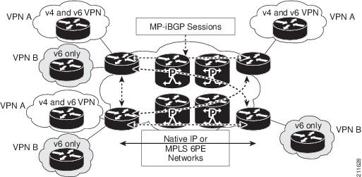
    6VPE method is being used to transport IPv6 traffic over the service provider network.

    IPv6 VPN Provider Edge Router (6VPE)

    Cisco

    Systems's 6VPE solution smoothly introduces IPv6 VPN service in a

    scalable way, without any IPv6 addressing restrictions. It does not

    jeopardize a well-controlled service provider IPv4 backbone or any

    customer networks. VPN service backbone stability is a key issue for

    those service providers who have recently stabilized their IPv4

    infrastructure. For IPv4 VPN customers, IPv6 VPN service is exactly the

    same as MPLS VPN for IPv4.

    The IPv6 MPLS VPN service model is

    similar to that of IPv4 MPLS VPNs. Service providers who have already

    deployed MPLS IPv4 VPN services over an IPv4 backbone can deploy IPv6

    MPLS VPN services over the same IPv4 backbone by upgrading the PE router

    IOS version and dual-stack configuration, without any change on the

    core routers. IPv4 services can be provided in parallel with IPv6

    services. A PE-CE link can be an IPv4 link, an IPv6 link, or a

    combination of an IPv4 and IPv6 link, as shown.

    211628.jpg


    IPv6

    VPN service is exactly the same as MPLS VPN for IPv4. 6VPE offers the

    same architectural features as MPLS VPN for IPv4. It offers IPv6 VPN and

    uses the same components, such as:
    • Multiprotocol BGP (MP-BGP) VPN address family
    • Route distinguishers
    • VPN Routing and Forwarding (VRF) instances
    • Site of Origin (SoO)
    • Extended community
    • MP-BGP
    The

    6VPE router exchanges either IPv4 or IPv6 routing information through

    any of the supported routing protocols, and switches IPv4 and IPv6

    traffic using the respective fast switching CEF or distributed CEF path

    over the native IPv4 and IPv6 VRF interfaces. The 6VPE router exchanges

    reachability information with the other 6VPE routers in the MPLS domain

    using Multiprotocol BGP, and shares a common IPv4 routing protocol (such

    as OSPF or IS-IS) with the other P and PE devices in the domain. Separate routing tables are maintained for the IPv4 and IPv6 stacks. A hierarchy of MPLS labels is imposed on an incoming customer IPv6 packet at the edge LSR:
    • Outer label (IGP Label) for iBGP next-hop, distributed by LDP.
    • Inner label (VPN Label) for the IPv6 prefix, distributed by MP-BGP.
    Incoming customer IPv6 packets at the 6VPE VRF interface are transparently forwarded inside the service provider's IPv4 core, based on MPLS labels. This eliminates the need to tunnel IPv6 packets. P routers inside the MPLS core are unaware that they are switching IPv6 labelled packets.
  • CSC flavor of MPLS Layer 3 VPN has MPLS enabled on PE-CE links.

    http://www.cisco.com/c/en/us/td/docs/ios/12_2s/feature/guide/fs2scsc.html

    CE router: A customer edge router is part of a customer network and interfaces to a provider edge (PE) router. In this document, the CE router sits on the edge of the customer carrier network.

    PE router: A provider edge router is part of a service provider's network connected to a customer edge (CE) router. In this document, the PE routers sits on the edge of the backbone carrier network.

    ASBR: In this document, an autonomous system boundary router connects one autonomous system to another.

    In this example, only the backbone carrier uses MPLS. The customer carrier (ISP) uses only IP. As a result, the backbone carrier must carry all the Internet routes of the customer carrier, which could be as many as 100,000 routes. This poses a scalability problem for the backbone carrier. To solve the scalability problem, the backbone carrier is configured as follows:
    • The backbone carrier allows only internal routes of the customer carrier (IGP routes) to be exchanged between the CE routers of the customer carrier and the PE routers of the backbone carrier.
    • MPLS is enabled on the interface between the CE router of the customer carrier and the PE router of the backbone carrier.
    Internal and external routes are differentiated this way:
    • Internal routes go to any of the routers within the ISP.
    • External routes go to the Internet.
    The number of internal routes is much smaller than the number of external routes. Restricting the routes between the CE routers of the customer carrier and the PE routers of the backbone carrier significantly reduces the number of routes that the PE router needs to maintain.

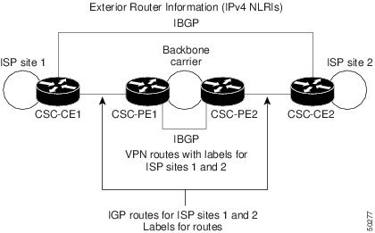
    Since the PE routers do not have to carry external routes in the VRF routing table, they can use the incoming label in the packet to forward the customer carrier Internet traffic. Adding MPLS to the routers provides a consistent method of transporting packets from the customer carrier to the backbone carrier. MPLS allows the exchange of an MPLS label between the PE and the CE routers for every internal customer carrier route. The routers in the customer carrier have all the external routes either through IBGP or route redistribution to provide Internet connectivity. Figure shows how information is exchanged when the network is configured in this manner.

    Figure Backbone Carrier Exchanging Routing Information with a Customer Carrier Who Is an ISP

    50277.jpg

  • Address-family l2vpn vpls-vpws MP-BGP address family must be configured to use VPLS autodiscovery in a Cisco IOS XR router.

    http://www.cisco.com/en/US/docs/ios/12_2sr/12_2srb/feature/guide/srbgpl2v.html
  • In MPLS Layer 3 VPN implementations, VRFs is used on the PE router to isolate potential overlapping routing information between different customers.
  • Within the service provider IP/MPLS core network, MP-BGP between the PE routers must be implemented to enable Layer 3 MPLS VPN services.
  • In MPLS Layer 3 VPN implementations, RT mechanism is used to control which routes are imported to a VRF.

    https://blog.initialdraft.com/archives/1537

    Route Target is a 64-bits BGP community used for tagging prefixes. When exporting prefixes from the VRF, we add to the prefixes a Route-Target community, so when the PE in the remote site has to import prefixes into the VRF, it can easily identify which prefixes to import.
  • Cisco 6PE operations:

    The top label in the label stack is assigned by LDP, and it is used to reach the egress PE.

    The inner label in the label stack is assigned by MP-BGP, and it is used for IPv6 forwarding at the egress PE.

    http://www.cisco.com/c/en/us/products/ios-nx-os-software/enterprise-ipv6-solution/index.html
 

PlAwAnSaI

Administrator
  • Address-family vpnv6 unicast Cisco IOS XR BGP configuration command is required to enable MP-BGP to carry IPv6 VPN routes.

    http://www.cisco.com/c/en/us/support/docs/ip/ip-version-6/112085-ipv6-over-mpls-vpn-00.html

    Introduction

    IP version 6 (IPv6) is a new version of IP designed to replace IP version 4 (IPv4), which is currently deployed and used extensively throughout the world. The benefits of IPv6 are primarily a result of its much larger addressing space, which is required to cope with the Internet expansion and with the explosion of Internet-capable appliances.

    An IPv6 VPN is connected over an IPv6 interface or sub-interface to the Service Provider (SP) backbone via a PE router. The site can be both IPv4 and IPv6 capable. Each IPv6 VPN has its own address space which means a given address denotes different systems in different VPNs. This is achieved via a new address-family, VPN-IPv6 or VPNv6 address-family, which prepends a Route Distinguisher (RD) to the IP address.

    A VPNv6 address is a 24-byte quantity beginning with an 8-byte RD and ending with a 16-byte IPv6 address. When a site is IPv4 and IPv6 capable, the same RD can be used for the advertisement of both IPv4 and IPv6 addresses.
  • router bgp 65101
    no bgp default ipv4-unicast
    neighbor 172.16.1.1 remote-as 65101
    neighbor 172.16.2.1 remote-as 65101
    neighbor 172.16.3.1 remote-as 65101
    !
    address-family ipv4
    neighbor 172.16.1.1 activate
    neighbor 172.16.3.1 activate
    !
    address-family vpnv4
    neighbor 172.16.2.1 activate
    neighbor 172.16.3.1 activate

    Only the 172.16.3.1 neighbor will receive both VPNv4 routes and IPv4 BGP routes.
  • When implementing MPLS Layer 3 VPNs with customers running OSPF as the CE-PE routing protocol, the service provider MPLS backbone looks like a superbackbone that is transparent to the CE OSPF routers.
  • When implementing MPLS Layer 3 VPNs with customers running OSPF as the CE-PE routing protocol, if there is a backdoor link between the CE routers, to ensure that the backdoor link is used only to back up the primary connection through the MPLS VPN will require a sham link to be implemented in the MPLS backbone.

    http://www.cisco.com/c/en/us/td/docs/ios-xml/ios/iproute_ospf/configuration/15-sy/iro-15-sy-book/iro-sham-link.html

    OSPF Sham-Link Support for MPLS VPN

    Feature History

    Release: 12.2(8)T

    Modification: This feature was introduced.

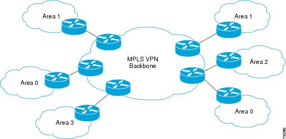
    This module describes how to configure and use a sham-link to connect Virtual Private Network (VPN) client sites that run the Open Shortest Path First (OSPF) protocol and share backdoor OSPF links in a Multiprotocol Label Switching (MPLS) VPN configuration.

    Feature Overview

    Using OSPF in PE-CE Router Connections

    In an MPLS VPN configuration, the OSPF protocol is one way you can conect customer edge (CE) routers to service provider edge (PE) routers in the VPN backbone. OSPF is often used by customers that run OSPF as their intrasite routing protocol, subscribe to a VPN service, and want to exchange routing information between their sites using OSPF (during migration or on a permanent basis) over an MPLS VPN backbone.

    The figure below shows an example of how VPN client sites that run OSPF can connect over an MPLS VPN backbone.

    70390.jpg

  • On Cisco IOS and IOS XE Layer 3 MPLS VPN implementations, when redistributing the customer RIP routes into MP-BGP, the RIP metric is copied into MED BGP attribute.
  • SOO extended BGP community option is used as a loop prevention mechanism to support MPLS VPN customers with multihomed sites.

    http://www.cisco.com/en/US/docs/ios/12_4t/12_4t11/htbgpsoo.html

    Site of Origin BGP Community Attribute

    The site-of-origin (SoO) extended community is a BGP extended community attribute that is used to identify routes that have originated from a site so that the re-advertisement of that prefix back to the source site can be prevented. The SoO extended community uniquely identifies the site from which a router has learned a route. BGP can use the SoO value associated with a route to prevent routing loops.
  • Refer to the partial Cisco IOS XR PE router configuration exhibit for

    supporting a Layer 3 MPLS VPN customer using BGP as the CE-to-PE routing

    protocol.

    router bgp 64500
    address-family vpnv4 unicast
    !
    vrf Customer_A
    address-family ipv4 unicast
    !
    neighbor 10.1.1.1
    remote-as 64501
    address-family ipv4 unicast

    The service provider AS number is 64500, the customer AS number is 64501, and the customer CE router is 10.1.1.1. The route distinguisher has not been configured under router bgp 64500 vrf Customer_A.

    http://www.cisco.com/en/US/docs/ios/12_2sr/12_2sra/feature/guide/srbgprid.html

    Route Distinguisher

    A router distinguisher (RD) creates routing and forwarding tables and specifies the default route distinguisher for a VPN. The RD is added to the beginning of an IPv4 prefix to change it into a globally unique VPN-IPv4 prefix. An RD can be composed in one of two ways: with an autonomous system number and an arbitrary number or with an IP address and an arbitrary number. You can enter an RD in either of these formats:
    • Enter a 16-bit autonomous system number, a colon, and a 32-bit number. For example: 45000:3
    • Enter a 32-bit IP address, a colon, and a 16-bit number. For example: 192.168.10.15:1
  • Based on the Cisco IOS XR VRF configuration exhibit,

    vrf CustomerA
    description Customer A Site
    address-family ipv4 unicast
    import route-target
    1:210
    !
    export route-target
    1:210
    !
    vrf CustomerB
    description Customer B Site
    address-family ipv4 unicast
    import route-target
    1:220
    !
    export route-target
    1:220
    !
    vrf CustomerA-C
    description Customer A Central Site
    address-family ipv4 unicast
    import route-target
    1:210
    1:1000
    !
    export route-target
    1:210
    1:1000
    !
    vrf CustomerB-C
    description Customer B Central Site
    address-family ipv4 unicast
    import route-target
    1:220
    1:1000
    !
    export route-target
    1:220
    1:1000

    The CustomerA central site can communicate with all CustomerA sites.

    The CustomerA central site can communicate with the CustomerB central site.
  • Refer to the partial Cisco IOS XR PE router VRF configuration exhibit.

    vrf customer1
    address-family ipv4 unicast
    import route-target
    1:1
    2:1
    !
    export route-target
    1:1
    2:2
    !
    vrf customer2
    address-family ipv4 unicast
    import route-target
    1:2
    2:1
    !
    export route-target
    1:2
    2:2

    To implement a central-service VPN supporting both customer1 and customer2, the required corresponding VRF configuration on the central-service-server PE router will be:

    vrf central-service-server
    address-family ipv4 unicast
    import route-target
    2:2
    3:1
    !
    export route-target
    2:1
    3:1
 

PlAwAnSaI

Administrator
  • Implementing a separate MPLS VPN to provide customers Internet access:

    The Internet gateway router will act as a CE router.

    Customers are assigned to the Internet VPN.
  • OSPF CE-to-PE routing protocol implements the down bit as a loop prevention mechanism.

    https://www.racf.bnl.gov/Facility/TechnologyMeeting/Archive/06-30-04-CISCO/Using-OSPF-in-MPLS-VPN-Environment.pdf

    OSPF Down Bit
    • An additional bit (Down bit) has been introduced in the Options field of the OSPF LSA header
    • PE-routers set the Down bit when redistributing routes from MP-BGP into OSPF
    • PE-routers never redistribute OSPF routes with Down bit set into MP-BGP
    One of the options bit in the LSA header has been allocated to be the down bit.

    The down bit is used between the PE-routers to indicate which routes were inserted into the OSPF topology database from the MPLS VPN super-backbone and thus shall not be redistributed back in the MPLS VPN super-backbone. The PE-router that redistributes the MP-BGP route as OSPF route into the OSPF topology database sets the down bit. Other PE-routers use the down bit to prevent this route from being redistributed back into MP-BGP.
  • When using OSPF as the CE-to-PE routing protocol in MPLS VPN implementations, an OSPF route from customerA site 1 in Area 0 will appear as interarea kind of OSPF route in customerA site 2, also in Area 0.
  • In Layer 3 MPLS VPN implementations, if some of the VPNv4 routes on one PE router do not appear on another PE router, RT export and import configuration errors could be the problem.

    https://blog.initialdraft.com/archives/1537
  • When implementing CSC services, using MP-BGP, IGP, and LDP methods can be used to exchange label information between the downstream CSC customer carrier and the CSC backbone carrier.

    http://www.cisco.com/c/en/us/td/docs/net_mgmt/ip_solution_center/5-2/mpls_vpn/user/guide/mpls52book/carrier.html#wp1058085

    Since the CSC-PE routers do not have to carry external routes in the VRF routing table, they can use the incoming label in the packet to forward the customer carrier Internet traffic. Adding MPLS to the routers provides a consistent method of transporting packets from the customer carrier to the backbone carrier. MPLS allows the exchange of an MPLS label between the CSC-PE and the CSC-CE routers for every internal customer carrier route. The routers in the customer carrier have all the external routes either through IBGP or route redistribution to provide Internet connectivity.

    When a backbone carrier and the customer carrier both provide BGP/MPLS VPN services, the method of transporting data is different from when a customer carrier provides only ISP services. The following list highlights those differences.
    • When a customer carrier provides BGP/MPLS VPN services, its external routes are VPN-IPv4 routes. When a customer carrier is an ISP, its external routes are IP routes.
    • When a customer carrier provides BGP/MPLS VPN services, every site within the customer carrier must use MPLS. When a customer carrier is an ISP, the sites do not need to use MPLS.
  • The Cisco IOS XR address-family ipv4 labeled-unicast and the Cisco IOS/IOS XE neighbor send-label commands are used in CSC using MP-BGP for label exchange MPLS implementation.

    http://www.cisco.com/c/en/us/td/docs/ios/12_0s/feature/guide/fscscleb.html

    The MPLS VPN - Carrier Supporting Carrier - IPv4 BGP Label Distribution feature lets you configure your carrier-supporting-carrier network to enable Border Gateway Protocol (BGP) to transport routes and Multiprotocol Label Switching (MPLS) labels between the backbone carrier provider edge (PE) routers and the customer carrier customer edge (CE) routers using multiple paths. Previously, you had to use Label Distribution Protocol (LDP) to carry the labels and an Internal Gateway Protocol (IGP) to carry the routes between PE and CE routers to achieve the same goal.

    The benefits of using BGP to distribute IPv4 routes and MPLS label routes are:
    • BGP takes the place of an IGP and LDP in a Virtual Private Network (VPN) forwarding/routing instance (VRF) table. You can use BGP to distribute routes and MPLS labels. Using a single protocol instead of two simplifies the configuration and troubleshooting.
    • BGP is the perferred routing protocol for connecting two Internet service providers (ISPs), mainly because of its routing policies and ability to scale. ISPs commonly use BGP between two providers. This feature enables those ISPs to use BGP.
  • When verifying Layer 3 MPLS VPN operations, show route vrf vrf-name Cisco IOS XR show command is best used to verify that the PE router is receiving the routes from the CE router.
  • When implementing Layer 3 MPLS VPNs on Cisco IOS/IOS XE PE routers, OSPF PE-to-CE routing protocol requires a separate routing process to be created for each VRF.
  • In Layer 3 MPLS VPN implementations, if a customer is using the same AS number at both customer sites and the PE-to-CE routing protocol is BGP, BGP AS override must be enabled on the PE router.

    https://supportforums.cisco.com/docs/DOC-21837

    Loop prevention in BGP is done by verifying the AS number in the AS Path. If the receiving router sees its own AS number in the AS Path of the received BGP packet, the packet is dropped. The receiving Router assumes that the packet was originated from its own AS and has reached the same place from where it originated initially.

    The feature could be a disaster if customers are using same AS number along the various sites and disallows customer sites having identical AS numbers to be linked by another AS number. In such a scenario, routing updates from one site will be dropped when the other site receives them.
  • Functions are performed by the PE router in an MPLS Layer 3 VPN:

    Exchanges routing updates with the CE router

    Exchanges VPNv4 routes with other PE routers over MP-BGP

    Translates the CE routing information into VPNv4 routes
  • RT BGP extended community is used to control the distribution of VPN routing information and to identify routers that may receive a set of routes that carry the community.
  • In config-bgp-vrf configuration mode is a route distinguisher configured in a Cisco IOS XR router.
  • Refer to the exhibit.

    route-policy filter
    pass
    end-policy
    !
    router bgp 1234
    bgp router-id 10.2.2.2
    address-family ipv4 unicast
    network 192.168.0.0/24
    network 192.168.1.0/24
    !
    neighbor-group share
    remote-as 1234
    update-source Loopback0
    address-family ipv4 unicast
    route-policy filter in
    route-reflector-client
    !
    neighbor 10.1.1.1
    use neighbor-group share
    !
    vrf INTERNET
    rd 1:1
    address-family ipv4 unicast
    redistribute connected

    The configured remote AS for neighbor 10.1.1.1 is 1234.

    The neighbor 10.1.1.1 cannot learn any routes from this router.
 

PlAwAnSaI

Administrator
  • L2TPv3 Layer 2 VPN technology is implemented over an IP core network without the need for MPLS.

    http://www.cisco.com/c/en/us/td/docs/ios/12_0s/feature/guide/l2tpv30s.html#wp1027129

    The

    Layer 2 Tunnel Protocol Version 3 feature expands on Cisco support of

    the Layer 2 Tunnel Protocol Version 3 (L2TPv3). L2TPv3 is an Internet

    Engineering Task Force (IETF) l2tpext working group draft that provides

    several enhancements to L2TP for the capability to tunnel any Layer 2

    payload over L2TP.

    Specifically, L2TPv3 defines the L2TP protocol

    for tunneling Layer 2 payloads over an IP core network using Layer 2

    virtual private networks (VPNs). Benefits of this feature include the

    following:
    • L2TPv3 simplifies deployment of VPNs
    • L2TPv3 does not require Multiprotocol Label Switching
    • L2TPv3 supports Layer 2 tunneling over IP for any payload
  • L2TPv3

    and AToM Layer 2 VPN methods support interworking between customer

    sites with different Layer 2 encapsulation at each end (for example,

    Frame Relay to Ethernet interworking).

    http://www.cisco.com/c/en/us/products/ios-nx-os-software/any-transport-over-multiprotocol-label-switching-atom/index.html

    Cisco

    Any Transport over MPLS (AToM) is a solution for transporting Layer 2

    packets over an MPLS backbone. It enables Service Providers to supply

    connectivity between customer sites with existing data link layer (Layer

    2) networks via a single, integrated, packet-based network

    infrastructure: a Cisco MPLS network. Without separate networks that

    each have network management environments, Service Providers can deliver

    Layer 2 connections over an MPLS backbone.

    Cisco AToM provides a

    common framework to encapsulate and transport supported Layer 2 traffic

    types over an MPLS network core. Service Providers can use a single

    MPLS network infrastructure to offer connectivity for supported Layer 2

    traffic and for IP traffic in Layer 3 VPNs.
  • Routed (interworking ip) and bridged (interworking ethernet) are the AToM interworking modes.

    http://www.cisco.com/c/en/us/td/docs/ios/ios_xe/mpls/configuration/guide/convert/mp_l2_vpns_book_xe/mp_l2vpn_intrntwkg_xe.html#wp1053845

    Interworking is a transforming function that is required to interconnect two heterogeneous attachment circuits (ACs). Several types of interworking functions exist. The function that is used would depend on the type of ACs being used, the type of data being carried, and the level of functionality required. The two main Layer 2 Virtual Private Network (L2VPN) interworking functions supported in Cisco IOS XE software are bridged and routed interworking.
  • When implementing EoMPLS on Cisco IOS XR routers, xconnect command under the l2vpn configuration mode is used to define the pseudowire.

    http://www.cisco.com/c/en/us/td/docs/wireless/asr_901/Configuration/Guide/b_asr901-scg/b_asr901-scg_chapter_01111.html

    Router(config-if-srv)# xconnect 11.205.1.1 141 encapsulation mpls

    Binds the VLAN attachment circuit to an Any Transport over MPLS (AToM) pseudowire for EoMPLS.

    xconnect peer-router-id vcid encapsulation mpls

    Example:
    Router(config)# xconnect 10.0.0.1 123 encapsulation mpls

    Binds the attachment circuit to a pseudowire VC. The syntax for this command is the same as for all other Layer 2 transports.
  • When configuring an EoMPLS PW on a Cisco IOS XR router, ethernet (Ethernet port mode) and vlan (VLAN-tagged mode) are the supported transport modes.
  • When implementing EoMPLS PWs, control word configuration is optional.
  • Pseudowire stitching method is used to provide inter-AS AToM services.

    http://www.cisco.com/c/en/us/td/docs/optical/cpt/r9_3/configuration/guide/cpt93_configuration/cpt93_configuration_chapter_0111.html#concept_3FB28D2411104926A1El2vpnpwstitch

    Understanding L2VPN Pseudowire Stitching

    L2VPN Pseudowire Stitching defines a static or dynamically configured set of two or more pseudowire segments that behave and function as a single point-to-point pseudowire. L2VPN Pseudowire Stitching enables L2VPN pseudowires to extend across two separate MPLS networks or across an inter-AS boundary, as shown in Figure 1 and Figure 2.

    L2VPN Pseudowire Stitching connects two or more contiguous pseudowire segments to form an end-to-end multihop pseudowire. This end-to-end pseudowire functions as a single point-to-point pseudowire.

    As shown in Figure 2, L2VPN Pseudowire Stitching enables you to keep the IP addresses of the edge PE routers private across inter-AS boundaries.

    Figure 1. L2VPN Pseudowire Stitching in an Intra-AS Topology
    127912.jpg


    Figure 2. L2VPN Pseudowire Stitching in an Inter-AS Topology
    127913.jpg

  • When troubleshooting EoMPLS configuration problems, pseudowire ID, control word usage, and MTU size parameters must match between the two ends of the pseudowire configurations.

    Provisioning an AToM Static Pseudowire

    In this configuration task, you use options in the xconnect Ethernet interface configuration command to specify a static connection, and mpls commands in xconnect mode to statically set the following pseudowire parameters:
    • Set the local and remote pseudowire labels
    • Enable or disable sending the MPLS control word
    SUMMARY STEPS
    1. Router> enable
      Enable privileged EXEC mode.
      • Enter your password if prompted.
    2. Router# configure terminal
      Enters global configuration mode.
    3. Router(config)# interface Ethernet 1/0
      Enters configuration mode for the specified interface.
    4. Router(config-if)# xconnect 10.131.191.252 100 encapsulation mpls manual pw-class mpls
      Configures a static AToM pseudowire and enters xconnect configuration mode where the local and remote psuedowire labels are set.
    5. Router(config-if-xconn)# mpls label 100 150
      Sets the local and remote pseudowire labels.
      • The label must be an unused static label within the static label range configured using the mpls label range command.
      • The mpls label command checks the validity of the label entered and displays an error message if it is not valid. The label supplied for the remote-pseudowire-label argument must be the value of the peer PE's local pseudowire label.
    6. Router(config-if-xconn)# no mpls control-word
      Sets whether or not the MPLS control word is sent.
      • This command must be set for Frame Relay data-link connection identifier (DLCI) and ATM adaptation layer 5 (AAL5) attachment circuits. For other attachment circuits, the control word is included by default.
      • If you enable inclusion of the control word, it must be enabled on both ends of the connection for the circuit to work properly.
      • Inclusion of the control word can be explicitly disabled using the no mpls control-word command.
      Haven't been able to find where MTU Must match.
 

PlAwAnSaI

Administrator
  • Frame Relay FECN, BECN, and DE bits Layer 2 protocol parameters can be

    carried inside the control word when implementing AToM service.

    http://www.cisco.com/en/US/products/ps6603/products_qanda_item09186a008009d4e3.shtml#wp39173

    Q. How does Frame Relay over MPLS work?

    A.

    Traffic is encapsulated in MPLS packets and forwarded across the MPLS

    network. When encapsulating Frame Relay over MPLS, the Frame Relay

    header and the frame check sequence (FCS) are stripped from the packet.

    The bits for Backward Explicit Congestion Notification (BECN), Forward

    Explicit Congestion Notification (FECN), Discard Eligibility (DE) and

    Command/Response (C/R) are carried across the MPLS network in the

    "Control Word" header.
  • When implementing VPLS on Cisco routers, VFI data

    structure resembles a virtual switch and is used for learning the MAC

    addresses.

    Restrictions for Implementing Virtual Private LAN Services on Cisco IOS XR Software

    The following restrictions are listed for implementing VPLS:
    • All attachment circuits in a bridge domain on an Engine 3 line card must be the same type (for example, port, dot1q, qinq, or qinany), value (VLAN ID), and EtherType (for example, 0x8100, 0x9100, or 0x9200). The Cisco CRS-1 router supports multiple types of attachment circuits in a bridge domain.
    • The Engine 3 line cards, cannot simultaneously have attachment circuits and MPLS-enabled on any one of its interfaces. The line card cannot be Edge-facing and Core-facing at the same time. Line cards on the Cisco CRS-1 router can be Edge-facing and Core-facing at the same time.
    • The line card requires ternary content addressable memory (TCAM) Carving configuration. The Cisco CRS-1 router however, does not require the TCAM Carving configuration.
    • Virtual Forwarding Instance (VFI) names have to be unique, because a bridge domain can have only one VFI.
    • On the Cisco CRS-1 router, a VPLS pseudowire (PW) can be configured only under VFI.
    • The Cisco CRS-1 router does not support VPLS with TE core tunnels.
    • A PW cannot belong to both a peer-to-peer (P2P) cross-connect group and a VPLS bridge-domain. This means that the neighboring IP address and the pseudowire ID have to be unique on the router, because the pseudowire ID is signaled to the remote provider edge.
    • You

      cannot manually set up a PW on one PE and use auto-discovery on the

      other PE to configure the same PW in the other direction. The auto-discovery feature is supported only on the Cisco XR 12000 Series Router.
  • In hierarchical VPLS implementations, 802.1ad and EoMPLS access architectures can be used between the UPE and NPE.

    http://www.cisco.com/c/en/us/td/docs/switches/metro/me3600x_3800x/software/release/12-2_52_ey/configuration/guide/3800x3600xscg/swmpls.html#wp1244272

    H-VPLS

    uses spoke connections, usually between Layer 2 switches acting as the

    CE and PE devices at the service provider's point-of presence (POP). The

    spoke connections can be either an IEEE 802.1Q tagged connection or an

    MPLS LSP.
  • LDP and BGP methods can be used for VPLS PW signaling.

    VPLS Discovery and Signaling

    VPLS is a Layer 2 multipoint service and it emulates LAN service across a WAN service. VPLS enables service providers to interconnect several LAN segments over a packet-switched network and make it behave as one single LAN. Service provider can provide a native Ethernet access connection to customers using VPLS.

    The VPLS control plane consists of two important components, autodiscovery and signaling:
    • VPLS Autodiscovery eliminates the need to manually provision VPLS neighbors. VPLS Autodiscovery enables each VPLS PE router to discover the other provider edge (PE) routers that are part of the same VPLS domain.
    • Once the PEs are discovered, pseudowires (PWs) are signaled and established across each pair of PE routers forming a full mesh of PWs across PE routers in a VPLS domain.
  • When implementing non-hierarchical VPLS with eight PE routers, 28 total PWs will be required between the PE routers.

    8 * ( 8 - 1 ) / 2
  • VPWS/EoMPLS offers E-Line type of Ethernet services as defined by the MEF.

    E-Line is based on a point-to-point Ethernet Virtual Connection. Two E-Line services are defined:
    • Ethernet Private Line (EPL): A very simple and basic point-to-point service characterized by low frame delay, frame delay variation, and frame loss ratio. No service multiplexing is allowed, and other than a committed information rate (CIR) no class of service (CoS) (Bandwidth Profiling) is allowed.
    • Ethernet Virtual Private Line (EVPL): A point-to-point service wherein service multiplexing (more than one Ethernet Virtual Connection) is allowed. The individual Ethernet Virtual Circuits can be defined with a rich set of Bandwidth Profiles and Layer 2 Control Protocol Processing methods as defined by the Metro Ethernet Forum.
  • When using the Cisco EVC software infrastructure, a double-tagged frame with a customer VLAN of 10 and a service provider VLAN of 150 will be best matched by encapsulation dot1q 150 configuration.
  • When implementing H-VPLS with QinQ access on Cisco Metro Ethernet switches, commands enable the QinQ tagging:

    switchport access vlan {sp-vlan}

    switchport mode dot1q-tunnel
  • Implementing H-VPLS instead of VPLS reduces having a full mesh of PWs between all the PE routers in the service provider MPLS core requirement.

    Hierarchical VPLS Overview

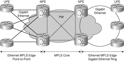
    Hierarchical VPLS (H-VPLS) provides scaling by only interconnecting the core MPLS NPE routers with a full mesh of PWs. The many UPE VPLS devices are then connected hierarchically by PWs to the NPE devices, not to each other. When there is redundancy, as shown in Figure, the software in the UPE blocks the PWs to all but the highest NPE IP address. H-VPLS partitions the network into several edge domains that are interconnected using an MPLS core.

    04fig11.jpg

    Figure: Hierarchical VPLS Overview

    One advantage of the H-VPLS approach for the service provider is that the core of the network is an MPLS network, which may also be used for the transport of Layer 3 MPLS VPNs and other traffic. The MPLS core also serves to limit any edge spanning-tree domains, speeding up STP convergence and reducing any potential instability.

    The physical topology of Ethernet Edge H-VPLS (EE H-VPLS) can comprise point-to-point Ethernet connections, or Ethernet rings using an STP to provide redundancy and loop avoidance. Other edge architectures use an aggregation layer between the UPE and NPE, or use Ethernet over SONET/SDH (EoS), or RPR as a transport between the UPE and NPE.
  • When implementing VPLS on Cisco IOS XR routers, the customer-facing subinterfaces on the PE routers are assigned to bridge domain Cisco EVC component.
  • Flexible frame-matching support and VLAN tag manipulation is an advantage of using the Cisco EVC infrastructure to implement carrier-class Ethernet services that are not available on non-EVC-capable platforms.
 

PlAwAnSaI

Administrator
  • When implementing a Layer 2 transport subinterface on a Cisco IOS XR

    router, default encapsulation option is used to match any packets that

    are not matched by any other service instances.

    encapsulation dot1q:
    Defines the matching criteria to map 802.1Q frames ingress on an interface to the appropriate service instance.

    encapsulation dot1ad dot1q:
    Defines

    the matching criteria to be used in order to map single-tagged 802.1ad

    frames ingress on an interface to the appropriate service instance.

    encapsulation dot1q second-dot1q:
    Defines the matching criteria to map Q-in-Q ingress frames on an interface to the appropriate service instance.

    encapsulation untagged:
    Defines the matching criteria to map untagged ingress Ethernet frames on an interface to the appropriate service instance.

    encapsulation default

    To

    configure the default service instance on a port, use the encapsulation

    default command in the Interface configuration mode. To delete the

    default service instance on a port, use the no form of this command.

    encapsulation default
    no encapsulation default

    Syntax Description:
    This command has no keywords or arguments.

    Command Default:
    No default service instance is configured on the port.

    Command Modes:
    Interface configuration

    This command was introduced since release 3.7.2.

    Usage Guidelines:

    To

    use this command, you must be in a user group associated with a task

    group that includes appropriate task IDs. If the user group assignment

    is preventing you from using a command, contact your AAA administrator

    for assistance.

    If the default service instance is the only one configured on a port, the encapsulation default command matches all ingress frames on that port. If the default service instance is configured on a port that has other non-default service instances, the encapsulation default command matches frames that are unmatched by those non-default service instances (anything that does not meet the criteria of other services instances on the same physical interface falls into this service instance).

    Only a single default service instance can be configured per interface. If you attempt to configure more than one default service instance per interface, the encapsulation default command is rejected.

    Only one encapsulation command must be configured per service instance.
  • When configuring VPLS on the Cisco ASR 9000, bridge-group, vfi, and bridge-domain configurations are required under the l2vpn configuration mode.
  • RP/0/RSP0/CPU0:R1(config)#int gigabitEthernet 0/6/0/0 l2transport is the command to define an interface as Layer 2 on the Cisco ASR 9000.

    Configuring Layer 2 Protocol Tunneling: Example

    Configuring L2PT in forward mode

    This example shows how to configure L2PT in the forward mode:

    At the customer facing router (encapsulation end):
    !
    interface GigabitEthernet0/1/0/1
    negotiation auto
    !
    interface GigabitEthernet0/1/0/1.1 l2transport
    encapsulation default
    l2protocol cpsv tunnel
    !
    interface GigabitEthernet0/1/0/2
    negotiation auto
    !
    interface GigibitEthernet0/1/0/2.1 l2transport
    encapsulation default
    !
    l2vpn
    xconnect group example
    p2p r1-connect
    interface GigabitEthernet0/1/0/1.1
    interface GigabitEthernet0/1/0/2.1
  • When implementing MPLS Layer 3 VPN services, BGP CE-PE routing method does not require the use of the redistribute command to enable the customer routes to be advertised through the MPLS cloud between the customer sites.
  • In MPLS Layer 3 VPN implementations, RD is used at the PEs to transform the customer IPv4 prefixes into a unique 96-bit prefix.
  • With Layer 3 MPLS VPN implementations on Cisco IOS XR PE routers, an interface is assigned to a VRF using the vrf command in RP/0/RP0/CPU0:pE(config-if)# configuration mode.
  • Refer to the partial Cisco IOS XR PE router configuration exhibit for

    supporting a Layer 3 MPLS VPN customer using EIGRP AS 20 as the CE-to-PE

    routing protocol.

    router eigrp 10
    vrf Customer_A
    address-family ipv4
    default-metric 10000 100 255 1 1500
    autonomous-system 20
    redistribute bgp 64500
    interface GigabitEthernet0/0/0/0
    !
    router bgp 64500
    vrf Customer_A
    rd 64500:1
    address-family ipv4 unicast
    redistribute eigrp 10

    The MPLS VPN customer is having problems receiving the EIGRP routes on the different customer site CE routers. The redistribute eigrp command is referencing the wrong AS number is wrong with this configuration that is causing the problem.
  • In RP/0/RP0/CPU0:pE(config-bgp-vrf-af)# Cisco IOS XR configuration mode is the redistribute static command applied to enable the redistribution of static VRF routes between the PE routers.

    http://www.cisco.com/en/US/docs/routers/asr9000/software/routing/configuration/guide/rcasr9kstat.html#wp1041359
  • Remove the IP address configuration on the interface, assign the VRF to the interface, and then reconfigure the IP address on the interface is required on a Cisco IOS XR router to assign an interface to a VRF.

    http://www.cisco.com/en/US/docs/ios_xr_sw/iosxr_r3.5/mpls/configuration/guide/gc35v3.html#wp1080845

    Configuring VRF Interfaces on PE Routers for Each VPN Customer

    Perform this task to associate a VPN routing and forwarding (VRF) instance with an interface or a subinterface on the PE routers.

    Note: You must remove IPv4/IPv6 addresses from an interface prior to assigning, removing, or changing an interface's VRF. If this is not done in advance, any attempt to change the VRF on an IP interface is rejected.
  • When implementing VPLS on Cisco IOS XR routers, the VPLS PW neighbors can be statically defined under vfi configuration mode.
  • On Cisco IOS XR platforms using the EVC infrastructure, interface gi0/0/0/0.10 l2transport command is used to enable a Layer 2 VPN subinterface.
  • In Layer 3 MPLS VPN implementations, MP-BGP protocol is used to carry the VPNv4 routes from PE to PE.
  • Packets are flooded on all other ACs and on all PWs that are associated with the bridge domain if the destination MAC address is not present in the table for the packets that are received on one of the ACs in VPLS.
  • show ip vrf [{detail | interfaces}] vrf-name

    The show ip vrf [{detail | interfaces}] vrf-name command shows detailed configurations about the VRF.


    Code:
    Pesaro# <b>show ip vrf detail Customer_A</b><br />
    VRF Customer_A; default RD 100:101<br />
    Interfaces:<br />
    Loopback101              Loopback111<br />
    Connected addresses are not in global routing table<br />
    Export VPN route-target communities<br />
    RT:100:1001<br />
    Import VPN route-target communities<br />
    RT:100:1001<br />
    No import route-map<br />
    No export route-map<br />
    <br />
    Pesaro# <b>show ip vrf interfaces</b><br />
    Interface              IP-Address      VRF              Protocol<br />
    Loopback101            200.0.6.1       Customer_A       up<br />
    Loopback111            200.1.6.1       Customer_A       up<br />
    Loopback102            200.0.6.1       Customer_B       up


    These commands allow you to verify:
    • That connected addresses are not in the global routing table.
    • The routing attributes of each VRF. What is exported on one side should be imported somewhere else.
    • The interface status (and IP addresses) of interfaces.
 

PlAwAnSaI

Administrator


  • Code:
    Router# <span style="color: Black; font-style: normal; font-weight: bold">show ip route<br />
    </span>


    Code:
    Codes: R - RIP derived, O - OSPF derived,<br />


    Code:
    C - connected, S - static, B - BGP derived,<br />


    Code:
    * - candidate default route, IA - OSPF inter area route,<br />


    Code:
    i - IS-IS derived, ia - IS-IS, U - per-user static route,<br />


    Code:
    o - on-demand routing, M - mobile, P - periodic downloaded static route,<br />


    Code:
    D - EIGRP, EX - EIGRP external, E1 - OSPF external type 1 route,<br />


    Code:
    E2 - OSPF external type 2 route, N1 - OSPF NSSA external type 1 route,<br />


    Code:
    N2 - OSPF NSSA external type 2 route<br />


    Code:
    Gateway of last resort is 10.119.254.240 to network 10.140.0.0<br />


    Code:
    O E2 10.110.0.0 [160/5] via 10.119.254.6, 0:01:00, Ethernet2<br />


    Code:
    E    10.67.10.0 [200/128] via 10.119.254.244, 0:02:22, Ethernet2<br><br>O:<br>Indicates the protocol that derived the route. It can be one of the following values:<br>
    • B - BGP derived
    • C - connected
    • D - Enhanced Interior Gateway Routing Protocol (EIGRP)
    • EX - EIGRP external
    • H - NHRP
    • i - IS-IS derived
    • ia - IS-IS
    • L - local
    • M - mobile
    • O - Open Shortest Path First (OSPF) derived
    • P - periodic downloaded static route
    • R - Routing Information Protocol (RIP) derived
    • S - static
    • U - per-user static route
    • o - on-demand routing
    • + - replicated route
E2:
Type of route. It can be one of the following values:
    • * - Indicates the last path used when a packet was forwarded. It pertains only to the nonfast-switched packets. However, it does not indicate which path will be used next when forwarding a nonfast-switched packet, except when the paths are equal cost.
    • E1 - OSPF external type 1 route
    • E2 - OSPF external type 2 route
    • IA - OSPF inter area route
    • L1 - IS-IS Level 1 route
    • L2 - IS-IS Level 2 route
    • N1 - OSPF not-so-stubby area (NSSA) external type 1 route
    • N2 - OSPF NSSA external type 2 route
10.110.0.0:
Indicates the address of the remote network.

[160/5]:
The first number in the brackets is the administrative distance of the information source; the second number is the metric for the route.

via 10.119.254.6:
Specifies the address of the next router to the remote network.

0:01:00:
Specifies the last time the route was updated (in hours:minutes:seconds).

Ethernet2:
Specifies the interface through which the specified network can be reached.


  • Code:
    Router# <b class="cCN_CmdName">show ip bgp vpnv4 all<br />
    </b>


    Code:
    BGP table version is 18, local router ID is 10.14.14.14<br />


    Code:
    Status codes: s suppressed, d damped, h history, * valid, > best, i - internal<br />


    Code:
    Origin codes: i - IGP, e - EGP,? - incomplete<br />


    Code:
    Network          Next Hop            Metric LocPrf Weight Path<br />


    Code:
    Route Distinguisher: 1:101 (default for vrf vpn1)<br />


    Code:
    *>i10.6.6.6/32       10.0.0.21              11    100      0 ?<br />


    Code:
    *> 10.7.7.7/32       10.150.0.2             11         32768 ?<br />


    Code:
    *>i10.69.0.0/30      10.0.0.21               0    100      0 ?<br />


    Code:
    *> 10.150.0.0/24     0.0.0.0                 0         32768 ?<br><br>BGP table version:<br>Internal version number of the table. This number is incremented whenever the table changes.<br><br>local router ID:<br>IP address of the router.<br><br>Status codes:<br>Status of the table entry. The status is displayed at the beginning of each line in the table. It can be one of the following values:<br>
    • s - The table entry is suppressed.
    • d - The table entry is dampened.
    • h - The table entry history.
    • * - The table entry is valid.
    • > - The table entry is the best entry to use for that network.
    • i - The table entry was learned via an internal BGP (iBGP) session.
    Origin codes:
    Origin of the entry. The origin code is placed at the end of each line in the table. It can be one of the following values:
    • i - Entry originated from an Interior Gateway Protocol (IGP) and was advertised with a network router configuration command.
    • e - Entry originated from an Exterior Gateway Protocol (EGP).
    • ? - Origin of the path is not clear. Usually, this is a router that is redistributed into BGP from an IGP.
    Network:
    IP address of a network entity.

    Next Hop:
    IP address of the next system that is used when forwarding a packet to the destination network. An entry of 0.0.0.0 indicates that the router has some non-BGP routes to this network.

    Metric:
    If shown, the value of the interautonomous system metric.

    LocPrf:
    Local preference value as set with the set local-preference route-map configuration command. The default value is 100.

    Weight:
    Weight of the route as set via autonomous system filters.

    Path:
    Autonomous system paths to the destination network. There can be one entry in this field for each autonomous system in the path.


PlAwAnSaI

Administrator
  • show ip vrf [vrf-name]

    The show ip vrf [vrf-name] command shows a

    summary of all VRFs present on the current router and their associated

    route-distinguishers and interface(s).

    Pesaro# show ip vrf
    Name Default RD Interfaces
    Customer_A 100:101 Loopback101
    Loopback111
    Customer_B 100:102 Loopback102

    This command allows you to verify:
    • The configuration of VRFs (and their names).
    • That each route-distinguisher (RD) is the same at each concerned PE.
 

PlAwAnSaI

Administrator
  • RP/0/RSP0/CPU0:router# show l2vpn xconnect detail

    Group siva_xc, XC siva_p2p, state is up; Interworking none
      Monitor-Session: pw-span-test, state is configured
    AC: GigabitEthernet0/4/0/1, state is up
    Type Ethernet
    MTU 1500; XC ID 0x5000001; interworking none; MSTi 0
    Statistics:
    packet totals: send 90
    byte totals: send 19056
    PW: neighbor 10.1.1.1, PW ID 1, state is up ( established ) : PW = PseudoWire
    PW class not set, XC ID 0x5000001
    Encapsulation MPLS, protocol LDP
    PW type Ethernet, control word enabled, interworking none
    PW backup disable delay 0 sec
    Sequencing not set
    MPLS Local Remote


    Label 30005 16003
    Group ID 0x5000300 0x5000400
    Interface GigabitEthernet0/4/0/1 GigabitEthernet0/4/0/2
           Interface   pw-span-test              GigabitEthernet0/3/0/1
    MTU 1500 1500
    Control word enabled enabled
    PW type Ethernet Ethernet
    VCCV CV type 0x2 0x2
    (LSP ping verification) (LSP ping verification)
    VCCV CC type 0x3 0x3
    (control word) (control word)
    (router alert label) (router alert label)


    Create time: 20/11/2007 21:45:07 (00:49:18 ago)
    Last time status changed: 20/11/2007 21:45:11 (00:49:14 ago)
    Statistics:
    packet totals: receive 0
    byte totals: receive 0

    Backup PW:
    PW: neighbor 2.2.2.2, PW ID 2, state is up ( established )
    Backup for neighbor 1.1.1.1 PW ID 1 ( standby )
    PW class not set, XC ID 0x0
    Encapsulation MPLS, protocol LDP
    PW type Ethernet, control word enabled, interworking none
    PW backup disable delay 0 sec
    Sequencing not set
    MPLS Local Remote


    Label 30006 16003
    Group ID unassigned 0x5000400
    Interface unknown GigabitEthernet0/4/0/2
  • 802.1ad and 802.1ah - IEEE
    VPWS and VPLS - IETF
    E-Line, E-LAN and E-Tree - MEF

    http://www.featbooks.com/read-online/vpls-and-vpws-at-a-glance-cisco-systems-inc
 
Top