CCNP Enterprise

PlAwAnSaI

Administrator
ENterprise designing and implementing Cloud Connectivity:

  1. enhanced Policy-Based Routing (ePBR) is used to direct packets that arrive at an interface to a specified next-hop. It is very useful in managing a large number of configured access lists more efficiently. In ePBR, router drops the traffic packets if the next hop configured in the PBR policy is not reachable. To avoid packet loss in such scenarios, must configure multiple next hops for each access control entry. Here are the steps to configure ePBR for IPv4 using Cisco vManage:
    1. Configure an extended ACL: This step involves defining the network or the host. For example, can permit IPv4 traffic from any source to specific hosts.
    2. Configure a class map that matches the ACL: Class maps match the parameters in the ACLs. For instance, can create a class map of type traffic and match it with the previously created ACL.
    3. Configure the policy map with the action to set the next hop: Policy maps with ePBR then take detailed actions based on the set statements configured. Can configure an ePBR policy map with the class map and set the next hop.
    4. Apply the service policy on the interface: Finally, apply the ePBR policy map to the interface. For example, can apply the policy map to a Gigabit Ethernet interface.
      .
  2. Security groups are a feature in AWS that allow to control the inbound and outbound traffic to instances. They act as a virtual firewall that can filter the traffic based on the source, destination, protocol, and port. Can assign one or more security groups to instances, and each security group can have multiple rules. Security groups are stateful, meaning that they automatically allow the response traffic for any allowed inbound traffic, and vice versa. Security groups are essential for securing nodes in the AWS EKS cluster, as they can prevent unauthorized access to database or other resources. Can also use security groups to isolate nodes from other instances in the same VPC or subnet, or to allow communication between nodes in different clusters or regions.

  3. ExpressRoute is a service that provides a dedicated, private, and high-bandwidth connection between the customer's on-premises network and Microsoft Azure cloud network.
    Private peering is a type of ExpressRoute circuit that allows the customer to access Azure services that are hosted in a virtual network, such as virtual machines, storage, and databases.
    Secure Data Center Interconnect (SDCI) is a Cisco solution that enables secure and scalable connectivity between multiple data centers and cloud providers, using technologies such as MPLS, IPsec, and SD-WAN.
    By using ExpressRoute with private peering and SDCI, the company can achieve the following benefits:
    • High availability: ExpressRoute circuits are redundant and resilient and can be configured with multiple service providers and locations for failover and load balancing. SDCI also provides high availability by using dynamic routing protocols and encryption mechanisms to ensure optimal and secure path selection.
    • Redundancy: ExpressRoute circuits can be paired together to form a redundant connection between the customer's network and Azure. SDCI also supports redundancy by allowing multiple connections between data centers and cloud providers, using different transport technologies and service levels.
    • Low latency: ExpressRoute circuits offer lower latency than public internet connections, as they bypass the congestion and variability of the internet. SDCI also reduces latency by using MPLS and SD-WAN to optimize the performance and quality of service for the traffic between data centers and cloud providers.
      .
  4. To enable the OMP advertisement of BGP routes for a specific VRF instance on a Cisco IOS XE SD-WAN device, the engineer must first configure the global address-family ipv4 and then enable bgp advertisement under the vrf definition. This will allow the device to advertise the BGP routes learned from the cloud provider to the OMP control plane, which will then distribute them to the other SD-WAN devices in the overlay network.

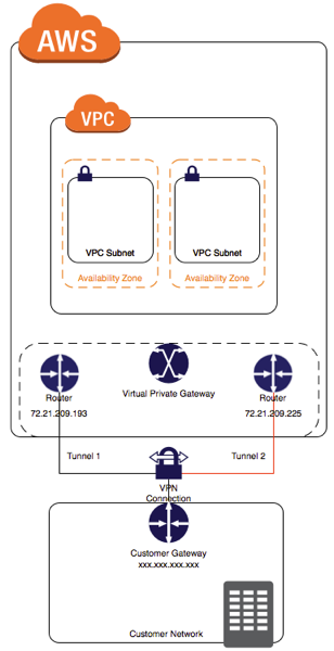
  5. An engineer needs to configure a site-to-site IPsec VPN connection between an on-premises Cisco IOS XE router and Amazon Web Services (AWS).
    Code:
    crypto keyring keyring-vpn-000001
      pre-shared-key address 20.20.20.29 key awskey01
    !
    crypto keyring keyring-vpn-000002
      pre-shared-key address 40.40.40.29 key awskey02
    !
    interface Tunnel1
      ip address 30.30.30.29 255.255.255.252
      tunnel destination 20.20.20.29
    !
    interface Tunnel2
      ip address 30.30.30.33 255.255.255.252
      tunnel destination 40.40.40.29
    !
    Two IP prefixes should be used to configure the AWS routing options are 20.20.20.0/24 & 40.40.40.0/24 because they are the IP prefixes that match the tunnel interfaces on the Cisco IOS XE router. The AWS routing options should include the local and remote IP prefixes that are used for the IPsec tunnel endpoints.

  6. The bgp advertise-best-external command is used to enable the advertisement of the best external path to internal BGP peers. This command is useful when there are multiple exit points from the local AS to other ASes, and the local AS wants to use the closest exit point for each destination. By default, BGP only advertises the best path to its peers, and the best path is usually the one with the lowest IGP metric to the next hop. However, this may not be the optimal path for traffic leaving the local AS, as it may result in suboptimal hot-potato routing or MED oscillations. The bgp advertise-best-external command allows BGP to advertise the best external path, which is the path with the lowest MED among the paths from different neighboring ASes, in addition to the best path. This way, the internal BGP peers can choose the best exit point based on the MED value, rather than the IGP metric.
    Code:
    https://ithitman.blogspot.com/2015/04/configuring-cisco-bgp-best-external.html

  7. The process of configuring a Cisco SD-WAN Cloud Interconnect with Equinix involves several steps:

    Cloud-Interconnect-wEquinix-copy.png
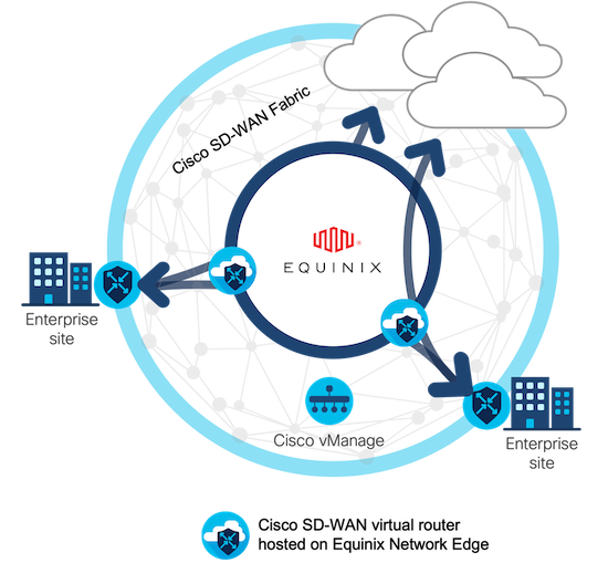
    1. This is the first step where ensure that there is the necessary UUIDs for the required number of Cisco SD-WAN Virtual Edge instances that want to deploy as Interconnect Gateways.
    2. After ensuring the availability of UUIDs, create the necessary network segments.
    3. After setting up the network segments, attach the Cisco SD-WAN Virtual Edge to the Equinix device template.
    4. Finally, create the Interconnect Gateway at the Equinix location that is closest to SD-WAN branch location.
      .
  8. An engineer must redistribute IBGP routes into OSPF to connect an on-premises network to a cloud provider.
    Code:
    https://github.com/ThaiCPE/encc/blob/main/README.md
    redistribute bgp 100 ospf 1 command redistributes the routes learned from BGP AS100 into OSPF Area 1, which allows router R3 to advertise those routes to router R2 and connect the on-premises network to the cloud provider.

  9. To redistribute OSPF internal routes into BGP:
    R3# router bgp 100
    redistribute ospf 1 > is used to redistribute OSPF routes from process ID 1 into BGP.
:cool:
 
Last edited:

PlAwAnSaI

Administrator
9+
  1. Cisco SD-WAN IPsec tunnels are different from native IPsec VPN tunnels in several ways. One of the unique features of Cisco SD-WAN IPsec tunnels is that they support real-time dynamic path selection, which means that they can automatically choose the best path for each application based on the network conditions and policies. This feature improves the performance, reliability, and efficiency of the network traffic. Native IPsec VPN tunnels, on the other hand, do not have this capability and rely on static routing or manual configuration to select the path for each tunnel. This can result in suboptimal performance, increased latency, and higher costs.

  2. The process of configuring an SLA class to specify the maximum packet loss, packet latency, and jitter allowed on a connection using Cisco vManage involves several steps.
    1. Click Configuration, select Policies, and then select Add Policy: This is the first step where navigate to the Policies section in the Configuration menu of Cisco vManage.
    2. Click SLA Class and then click New SLA Class List: In this step, create a new SLA Class List.
    3. After setting up the SLA Class List, Select the Criteria for the SLA class, select Loss, Latency and Jitter, and then click Add.
    4. Finally, Set values for Loss, Latency, Jitter, and App Probe Class.
      .
  3. To configure a custom application with Cisco SD-WAN centralized policy using Cisco vManage, need to follow these steps:
    1. Click Configuration, select Policies, and then select Centralized Policy.
    2. Click Custom Options, select Centralized Policy, and then select Lists.
    3. After setting up the Lists, Click Custom Applications, and then select New Custom Application.
    4. Finally, enter a name for the application, enter/specify the match criteria, and then click Add to complete the configuration.
      .
  4. The process of configuring an application-aware routing policy in Cisco vManage involves several steps:
    1. Create the groups of interest: This is the first step where define the applications or groups that the policy will affect.
    2. Configure the topology: This involves setting up the network topology that the policy will operate within.
    3. After setting up the groups and topology, then create the application-aware routing policy. This policy tracks network and path characteristics of the data plane tunnels between Cisco SD-WAN devices and uses the collected information to compute optimal paths for data traffic.
    4. Finally, Apply the application-aware routing policy to a specific VPN and sites: This allows the policy to affect the desired network traffic.
      .
  5. The process of configuring a CLI add-on feature template in Cisco vManage for ePBR for IPv4 involves several steps:
    1. Click Configuration, select Templates, and then select Feature Templates.
    2. Click Add a new Template, select the device, and then click Select Template.
    3. After setting up the template, Click/select CLI Add-On Template option, and then enter the name and description for the template.
    4. Finally, Paste the CLI configuration into the template and then click Save the changes.
      .
  6. The process of editing the settings of a site-to-site IPsec VPN connection between an on-premises Cisco IOS XE router and AWS and configuring IPsec to support multiple peers and failover after 120 seconds of idle time on the first entry of the crypto map named Cisco involves several steps:
    1. crypto map cisco 1 ipsec-isakmp: This command is used to create a new entry in the crypto map named
      "cisco". The "1" is the sequence number of the entry, and "ipsec-isakmp" specifies that the IPSec Security Associations (SAs) should be established using the Internet Key Exchange (IKE) protocol.
    2. set peer [192.168.10.1] default: This command is used to specify the IP address of the default peer for the crypto map entry.
    3. set peer [192.168.20.1]: This command is used to add an additional peer to the crypto map entry. This allows the IPsec VPN to support multiple peers.
    4. set security-association idle-time [120] default: This command is used to set the idle time for the security association. If no traffic is detected over the VPN for the specified idle time (120 seconds), the security association is deleted, and the VPN connection fails over to the next peer.
      .
  7. The process of configuring an Application Quality of Experience (AppQoE) service node for WAN optimization for applications that are hosted in the cloud using Cisco vManage for C8000V or C8500L-8S4X devices involves several steps:
    1. Navigate to Configuration, select Templates, and then select Device Templates.
    2. Click Create a new Template, select From Feature Template, and then select the device model from the feature template.
    3. After setting up the template, select the device and the service node, and then set the template name and description.
    4. Finally, attach the created device template to the device.
      .
  8. The configuration of cloud connectivity with Cisco Umbrella Secure Internet Gateway (SIG) in active/backup mode involves several steps. After configuring the SIG Credentials and SIG Feature Templates, the engineer must:
    1. Select the SIG provider for the primary tunnel: This is the first step in setting up the active/backup mode. The primary tunnel is the main connection path for the cloud connectivity.
    2. Add the secondary tunnel: The secondary tunnel serves as a backup in case the primary tunnel fails. It ensures that the cloud connectivity remains uninterrupted even if there are issues with the primary tunnel.
    3. Create one high-availability pair using primary and secondary tunnels: This step involves pairing the primary and secondary tunnels to create a high-availability pair. This ensures that the cloud connectivity will switch over to the secondary tunnel seamlessly if the primary tunnel fails.
    4. Edit the service-side VPN template to inject a service route: The final step involves modifying the VPN template on the service side to include a service route. This ensures that the traffic is correctly routed through the primary or secondary tunnel as needed.
      .
  9. show sdwan system status: This command is used to display the time and process information of the device, as well as CPU, memory, and disk usage data.
    show policy-firewall config: This is used to validate the configured zone-based firewall.
    show sdwan policy app-route-policy-filter: is used to display information about application-aware routing policy matched packet counts on the Cisco IOS XE SD-WAN devices.
    show sdwan security-info: used to view the security information that is configured for IPsec tunnel connections

  10. The process of configuring a site-to-site VPN connection between an on-premises Cisco IOS XE router and AWS involves several steps:

    Multiple_VPN_Tunnels_diagram.png

    .
    1. Create a Customer GateWay (CGW) in AWS: This is the first step where define the public IP address of on-premises Cisco IOS XE router in AWS.
    2. Create a Virtual private GateWay (VGW) and attaching it to the VPC in AWS.
    3. After setting up the CGW and VGW, then create a site-to-site VPN connection in AWS: This involves specifying the CGW, VGW, and the static IP prefixes for on-premises network.
    4. After the AWS side is set up, Configure the on-premises Cisco IOS XE router with the required IPsec VPN parameters and routing settings.
    5. Finally, Verify and test the VPN connection to ensure that it is working correctly.
:cool:
 
Last edited:

PlAwAnSaI

Administrator
19+
  1. The process of configuring a site-to-site IPsec VPN connection between an on-premises Cisco IOS XE router in Controller mode and AWS and changing the IKE version from IKEv1 to IKEv2 in Cisco vManage involves several steps:
    1. Click Configuration, select Templates, and then select Feature Templates.
    2. Click Add Template, select the device, and then click Basic Configuration.
    3. Before changing the IKE version, need to Shut down the existing tunnel and then remove the ISAKMP profile that is configured for IKEv1.
    4. Finally, Attach the newly created IKEv2 profile to the tunnel and then run the no shutdown command on the tunnel to bring the tunnel back up.
      .
  2. A fully meshed topology provides high availability by eliminating single points of failure and allowing multiple paths between branch offices.
    SD-WAN technology enables multihoming by supporting multiple transport options, such as MPLS, internet, LTE, etc. SD-WAN also provides QoS by applying policies to prioritize traffic based on application, user, or network conditions.
    Dynamic routing allows the SD-WAN solution to adapt to changing network conditions and optimize the path selection for each traffic type.
    A fully meshed topology with SD-WAN technology can also support specific routing needs, such as segment routing, policy-based routing, or application-aware routing.

  3. Code:
    vedge1# show policy from-vsmart
    apply-policy
      site-list site1
        control-policy prefer_local out
      !
      policy
        lists
          site-list site1
            site-id 100
          tloc-list prefer_sitel
            tloc 10.1.1.1 color mpls encap ipsec preference 100
          control-policy prefer_local
            sequence 10
              match route
                site-list sitel
            !
            action accept
              set
                tloc-list prefer_site1
    A centralized data policy is a policy that is applied to all devices in the overlay network, regardless of the site list.
    A localized data policy is a policy that is applied only to the devices that are listed in the site list.

  4. Configuration example of a site-to-site IPsec VPN connection between an on-premises Cisco IOS XE router and AWS:
    Code:
    crypto keyring keyring-vpn-000001
      pre-shared-key address 192.10.10.10 key secretkey01
    !
    interface Tunnel1
      ip address 20.20.20.21 255.255.255.252
      tunnel destination 192.10.10.10
    !
    crypto ikev2 keyring AWS_Keyring
      peer AWS Peer
      tunnel source 20.20.20.21
        pre-shared-key local awssecretkey01
      pre-shared-key remote awsecretkey02

  5. The end-to-end ping between the office user PC and the AWS EC2 instance is not working because either the security group rules for the host VPC (VNET for Azure) are blocking the ICMP traffic or the IPsec SA counters are showing errors or drops. To diagnose the loss of connectivity, the engineer should check both the security group rules and the IPsec SA counters.
    If the site-to-site VPN tunnel is not up and the site-to-site routing is not work correctly, the IPsec SA configuration on the Cisco VPN router and the AWS private virtual gateway may likely to be the cause of the problem.

    1665595978555


  6. Cisco lKEv2 configuration brings up the IPsec tunnel between the remote office router and the AWS virtual private gateway:
    Code:
    crypto ikev2 proposal Prop-DEMO
      encryption aes-cbc-128
      integrity sha1
      group 2
    !
    crypto ikev2 policy POL-DEMO
      match address local 209.165.202.105
      proposal Prop-DEMO
    !
    crypto ikev2 keyring DEMO-Keyring
      peer Cisco-AWS
      address 209.165.201.1
      pre-shared-key DEMOlabCisco12345
    !
    crypto ikev2 profile PROFILE-PoC
      match address local 209.165.201.1
      match identity remote address 209.165.202.105 255.255.255.255
      authentication remote pre-share
      authentication local pre-share
      keyring local DEMO-Keyring
    !

  7. The role of service providers to establish private connectivity between on-premises networks and Google Cloud resources is to facilitate direct, dedicated network connections through Google Cloud Interconnect.
    Google Cloud Interconnect is a service that allows customers to connect their on-premises networks to Google Cloud through a service provider partner. This provides low latency, high bandwidth, and secure connectivity to Google Cloud services, such as Google Compute Engine, Google Cloud Storage, and Google BigQuery.
    Google Cloud Interconnect also supports hybrid cloud scenarios, such as extending on-premises networks to Google Cloud regions or connecting multiple Google Cloud regions together. Google Cloud Interconnect offers two types of connections: Dedicated Interconnect and Partner Interconnect.
    • Dedicated Interconnect provides physical connections between the customer's network and Google's network at a Google Cloud Interconnect location.
    • Partner Interconnect provides virtual connections between the customer's network and Google's network through a supported service provider partner.
      Both types of connections use VLAN attachments to establish private connectivity to Google Cloud Virtual Private Cloud (VPC) networks.
      .
  8. To send traffic into an IPsec tunnel to the cloud VPN gateway, the engineer must configure two actions:
    1. Configure access lists that match the interesting user traffic. This is the traffic that needs to be encrypted and sent over the IPsec tunnel. The access lists are applied to the crypto map that defines the IPsec parameters for the tunnel.
    2. Configure Policy-Based Routing (PBR). This is a technique that allows the engineer to override the routing table and forward packets based on a defined policy. PBR can be used to send specific traffic to the IPsec tunnel interface, regardless of the destination IP address. This is useful when the cloud VPN gateway has a dynamic IP address or when multiple cloud VPN gateways are available for load balancing or redundancy.
      .
  9. A highly secure multitier application in AWS that includes S3, RDS, and some additional private links requires specific routing and bucket policies to keep the traffic safe. The reasons are as follows:
    • Specific routing policies are needed to ensure that the traffic between the tiers is routed through the private links, which provide secure and low-latency connectivity between AWS services and on-premises resources. The private links can also prevent the exposure of the data and the application logic to the public internet.
    • Bucket policies are needed to control the access to the S3 buckets that store the application data. Bucket policies can specify the conditions under which the requests are allowed or denied, such as the source IP address, the encryption status, the request time, etc. Bucket policies can also enforce encryption in transit and at rest for the data in S3.
:cool:
 
Last edited:
Top