PlAwAnSaI
Administrator
Service Provider Routing and Switching Certification Track:

www.juniper.net/us/en/training/certification/certification-tracks/sp-routing-switching-track
AND MOST OF THE JUNIPERS EQUIPMENT:
FORWARDING PLANE:
The Basics:
Platforms Running the Junos OS
Code:
http://mozquito-network.blogspot.com/2013/11/configure-junos-part-1.html
Juniper Networks Certified Internet Associate (JNCIA) Study Guide
Juniper Networks Certified Internet Professional (JNCIP) Study Guide
Juniper Networks Certified Internet Expert (JNCIE) Study Guide
Code:
https://kb.juniper.net/kb/documents/public/junos/StudyGuides

A packet is received on an interface (1,2) and is segmented into J-cells by the I/O Manager ASIC (3). The Distributed Buffer Manager ASIC stores the packet in the shared memory pool (4-6). The Internet Processor ASIC performs a route lookup (7) and sends the result to the Distributed Buffer Manager ASIC (
 , which forwards it to the outgoing I/O Manager ASIC (9). After queuing the packet, the I/O Manager ASIC receives the J-cells from the memory pool (10) and re-forms the packet (11). It is sent to the outgoing PIC I/O Manager ASIC for transmission into the network (12).

www.juniper.net/us/en/training/certification/certification-tracks/sp-routing-switching-track
- Juniper Networks Learning Paths:
www.juniper.net/assets/cn/zh/local/pdf/training/certification-paths-by-credential.pdf
- sh configuration,sh ver,show interface terse,show interfaces [intfc] detail,show route,..
networking.ringofsaturn.com/Cisco/ciscojuniper.php
- JUNOS Internet Software Configuration Guide: Getting Started
www.juniper.net/techpubs/software/junos/junos57/swconfig57-getting-started/html
- mellowd.co.uk/ccie/?paged=8&tag=juniper
- It's Different and That's Okay
- It's Cool
- FreeBSD UNIX
- Modular Architecture
- Independent Process
- Hierarchy of Design
AND MOST OF THE JUNIPERS EQUIPMENT:
- From Branch to Core
- From Router to Switch to Firewall
- Same Source Code Base
FORWARDING PLANE:
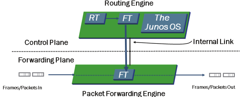
- Control is Key
- Routing Engine (RE)
- Routing Table (RT)
- Forwarding Table (FT)
- Packet Forwarding Engine (PFE)
- Completely Separate Planes
- Is the Intelligence of the Platform
- Routing Tables
- Bridging Table
- Primary Forwarding Engine
- ASIC Based
- Forwarding Table Copy
- It does the Leg Work
The Basics:
- % cli = ena
- > edit / configure = conf t
- # set system root-authentication plain-text-password = username root password
- # show system = sho run xxx
- # show system | display set
- # show interface | display set = sho run int
- > show interfaces terse = sho ip int bri
- > show configuration | display set
Platforms Running the Junos OS
- M Series Multiservice Routers can be deployed in both high-end enterprise and service-provider environments.
- T Series Core Routers is ideal for service provider environments and is deployed within the core of those networks.
- J Series Services Routers are deployed at a branch and remote locations in the network.
- MX Series Ethernet Services Routers is targeted for dense dedicated access aggregation and provide edge services in medium and large POPs.
- EX Series Ethernet Switches are designed for access, aggregation, and core deployments and are well for enterprise and data center.
- SRX Series Services Gateways is designed to meet the network and security in both enterprise and service provider environments.
- The Junos OS is compartmentalized into multiple software processes. Each process runs in its own protected memory space, ensuring that one process cannot directly interfere with another. This modularity also ensures that new features can be added with less likelihood of breaking current functionality are some advantages of the Junos OS.
- The primary functions of the control plane are to maintain routing intelligence, control and monitor the chassis, and manage the Packet Forwarding Engine (PFE). The primary functions of the forwarding plane are to forward packets and to implement advanced services.
- Transit traffic is forwarded through the PFE on platforms running the Junos OS, based on the forwarding table installed on the PFE. Exception traffic is processed locally by the platform running the Junos OS by either the PFE or the RE depending on the type of traffic. Host-bound packets, such as protocol and management traffic, are passed directly to the RE for processing, while traffic requiring ICMP error message responses is typically handled by the PFE.
- > ?
- > clear ?
- > help topic interfaces ?
- > help topic interfaces address
- > help reference interfaces address
- edit - functions like a CD command
- up - moves up one level
- up n - moves up n levels
- top - moves to the top of the hierarchy
- exit - moves to the previous, higher level in the hierarchy or exits configuration mode if at the top level of the hierarchy
- Two primary modes exist within the Junos OS: the operational mode and the configuration mode. A third mode also exists in the form of the FreeBSD shell.
Type configure at the operational mode prompt to enter configuration mode which allows to make configuration changes.
- Use the operational mode to monitor and troubleshoot the software, network connectivity, and hardware. Use the configuration mode to configure a device running the Junos OS, including interfaces, protocols, user access, and system hardware.
- Use the Spacebar to complete a command and the Tab key to complete a variable.
- The top command is the quickest method of returning to the top of the hierarchy.
- The active configuration has been committed and is in use, whereas the candidate configuration is not active until performing a commit operation.
- The show | compare command displays the differences between the currently active and candidate configurations.
Code:
http://mozquito-network.blogspot.com/2013/11/configure-junos-part-1.html
Juniper Networks Certified Internet Associate (JNCIA) Study Guide
Juniper Networks Certified Internet Professional (JNCIP) Study Guide
Juniper Networks Certified Internet Expert (JNCIE) Study Guide
Code:
https://kb.juniper.net/kb/documents/public/junos/StudyGuides
- The Routing Engine is the intelligence of the router. It operates the routing protocols and builds a routing and forwarding table. The forwarding table is copied to the Packet Forwarding Engine, where the actual transmission of user data packets is handled.
- The JUNOS software is stored on the internal flash drive, the internal hard drive, and the removable flash media. When the router begins to boot, the removable media is checked first, followed by the internal flash drive, and finally the internal hard drive.
- May save the router's configuration to the hard drive with the save command. The load command restores files to the candidate configuration. The candidate configuration becomes the active configuration with the commit command. Can easily return to a previous configuration with the rollback command.
- There are four main ASICs used in the Packet Forwarding Engine: the Internet Processor ASIC, the Distributed Buffer Manager ASIC, the I/O Manager ASIC, and the PIC I/O Manager ASIC.
A packet is received on an interface (1,2) and is segmented into J-cells by the I/O Manager ASIC (3). The Distributed Buffer Manager ASIC stores the packet in the shared memory pool (4-6). The Internet Processor ASIC performs a route lookup (7) and sends the result to the Distributed Buffer Manager ASIC (