Deploying Cisco Service Provider Advanced Routing (SPADVROUTE)

PlAwAnSaI

Administrator
  • You noticed a recent change to the BGP configuration on a PE router, the bgp scan time has been changed from the default value to 30s. Effects will this change have:

    The BGP table will be examined and verified more frequently.

    The BGP table will be modified more quickly in the event that a next-hop address becomes unreachable.

    The CPU load of the router will increase.

    bgp scan-time

    To configure scanning intervals of Border Gateway Protocol (BGP) routers for next hop validation or to decrease import processing time of Virtual Private Network version 4 (VPNv4) routing information, use the bgp scan-time command in address family or router configuration mode. To return the scanning interval of a router to its default scanning interval of 60 seconds, use the no form of this command.

    bgp scan-time [import] scanner-interval
    no bgp scan-time [import]
    scanner-interval

    import = (Optional) Configures import processing of VPNv4 unicast routing information from BGP routers into routing tables.

    scanner-interval = The scanning interval of BGP routing information. Valid values are from 15 to 60 seconds. The default is 60 seconds.
  • On Cisco IOS-XR, BGP speaker process can be distributed into multiple instances.

    Cisco IOS XR allows you to control the configuration of the number of distributed speakers and enables you to selectively assign neighbors to specific speakers. On the CRS-1 platform, multiple speaker processes up to 15 may be configured. However, configuring all the different speakers on the primary route processor simply adds to the load on the single RP. Distributed speaker functionality is useful if Distributed Route Processor (DRP) hardware is available to take advantage of process placement.

    In addition to the speaker process, BPM starts the bRIB process once BGP is configured. bRIB process is responsible for performing the best-path calculation based on partial best paths received from the speaker processes. The best route is installed into the bRIB and is advertised back to all speakers. The bRIB process is also responsible for installing routes in the RIB and for handling routes redistributed from the RIB.
  • Refer to the configuration exhibit, taken from a Cisco IOS-XR router.

    router static
    address-family ipv4 unicast
    192.0.2.1/32 Null0
    !
    route-policy RTBH
    if tag is 666 then
    set next-hop 192.0.2.1
    endif
    end-policy
    !
    router bgp 65123
    address-family ipv4 unicast
    redistribute static route-policy RTBH
    !
    !When attacks are detected from 209.165.201.144/28
    !
    router static
    address-family ipv4 unicast
    209.165.201.144/28 null0 tag 666
    !

    Set community (no-export) in the route policy is configuration change required to properly enable this router as

    the signaling router for implementing source-based RTBH filtering.
  • Refer to the Cisco IOS-XR BGP configuration exhibit.

    route-policy passall
    permit
    end-policy
    !
    router bgp 65123
    af-group abc address-family ipv4 unicast
    route-policy passall in
    route-policy passall out
    !
    neighbor-group efg
    password C!sc0!3o
    ttl-security
    update-source Loopback0
    maximum-prefix 10
    address-family ipv4 unicast
    use af-group abc
    !
    neighbor 209.165.201.130
    remote-as 65234
    use neighbor-group efg

    The maximum-prefix 10 configuration should be configured under the af-group abc instead of the neighbor-group efg.

    The passall route policy is wrong.

    http://www.cisco.com/c/en/us/support/docs/ip/border-gateway-protocol-bgp/25160-bgp-maximum-prefix.html
  • The RPF check when a multicast packet arrives at a router:

    The router looks up the source address in

    the unicast routing table to determine if the packet has arrived on the

    interface that is on the reverse path back to the source.

    If

    the packet has arrived on the interface leading back to the source, the

    RPF check passes and the packet is forwarded. If the RPF check fails,

    the packet is dropped.

    Reverse Path Forwarding (RPF)

    RPF is a fundamental concept in multicast routing that enables routers to correctly forward multicast traffic down the distribution tree. RPF makes use of the existing unicast routing table to determine the upstream and downstream neighbors. A router will only forward a multicast packet if it is received on the upstream interface. This RPF check helps to guarantee that the distribution tree will be loop free.

    RPF Check

    When a multicast packet arrives at a router, the router will perform an RPF check on the packet. If the RPF check is successful, the packet will be forwarded. Otherwise it will be dropped. For traffic flowing down a source tree, the RPF check procedure works as follows:

    Step 1. Router looks up the source address in the unicast routing table to determine if it has arrived on the interface that is on the reverse path back to the source.

    Step 2. If packet has arrived on the interface leading back to the source, the RPF check is successful and the packet will be forwarded.

    Step 3. If the RPF check in 2 fails, the packet is dropped.
  • Refer to the Cisco IOS-XR show output exhibit.

    RP/0/RSP0/CPU0:p1# show bgp neighbor 10.1.1.1 configuration
    Wed Oct 26 17:45:09.690 UTC
    neighbor 10.1.1.1
    remote-as 64500 [ ]
    update-source Loopback0 [ ]
    address-family IPv4 Unicast [ ]

    The [ ] indicates the configuration was not inherited from a group.

    show bgp neighbors

    Use the show bgp neighbors command to display information about the BGP configuration for neighbors.

    - Use the configuration option to display the effective configuration for the neighbor, including any settings that have been inherited from session groups, neighbor groups, or af-groups used by this neighbor.

    - Use the inheritance option to display the session groups, neighbor groups, and af-group from which this neighbor inherits configuration settings.

    The following example displays sample output from the show bgp af-group command using the configuration keyword. This example shows where each configuration item was inherited from. The default-originate command was configured directly on this address family group (indicated by [ ]). The remove-private-as command was inherited from address family group GROUP_2, which in turn inherited from address family group GROUP_3:

    RP/0/0/CPU0:router# show bgp af-group GROUP_1 configuration

    af-group GROUP_1 address-family ipv4 unicast
    capability orf prefix-list both [a:GROUP_2]
    default-originate [ ]
    maximum-prefix 2500 75 warning-only [ ]
    policy POLICY_1 in [a:GROUP_2 a:GROUP_3]
    remove-private-AS [a:GROUP_2 a:GROUP_3]
    send-community-ebgp [a:GROUP_2]
    send-extended-community-ebgp [a:GROUP_2]
 

PlAwAnSaI

Administrator
  • When enabling interdomain multicast routing:

    Noncongruent unicast and multicast topologies can be supported using multiprotocol BGP.

    Use MSDP to enable the RPs from different domains to exchange information about active multicast sources.

    http://networkstechnote.wordpress.com/2010/08/11/mbgp-msdp

    MSDP

    In

    the PIM-SM model, multicast sources and receivers must register with

    their local RP. Actually, the router closest to the sources or receivers

    registers with the RP, but the key point to note is that the RP knows

    about all the sources and receivers for any particular group. RPs in

    other domains have no way of knowing about sources located in other

    domains. MSDP is an elegant way to solve this problem.

    MSDP is a mechanism that allows RPs to share information about active sources.

    RPs know about the receivers in their local domain. When RPs in remote

    domains hear about the active sources, they can pass on that information

    to their local receivers and multicast data can then be forwarded

    between the domains. A useful feature of MSDP is that it allows each

    domain to maintain an independent RP that does not rely on other

    domains, but it does enable RPs to forward traffic between domains.

    PIM-SM is used to forward the traffic between the multicast domains.

    The RP in each domain establishes an

    MSDP peering session using a TCP connection with the RPs in other

    domains or with border routers leading to the other domains. When the RP

    learns about a new multicast source within its own domain
    (through the normal PIM register mechanism), the

    RP encapsulates the first data packet in a Source-Active (SA) message

    and sends the SA to all MSDP peers. The SA is forwarded by each

    receiving peer using a modified RPF check,
    until the SA reaches every MSDP router in the interconnected networks - theoretically the entire multicast internet. If the receiving MSDP peer is an RP, and the RP has a (*, G) entry for the group in the SA (there is an interested receiver), the RP creates (S, G) state for the source and joins to the shortest path tree for the source. The encapsulated data is decapsulated and forwarded down the shared tree of that RP. When the packet is received by the last hop router of the receiver, the last hop router also may join the shortest path tree to the source. The MSDP speaker periodically sends SAs that include all sources within the own domain of the RP.

    http://www.cisco.com/c/en/us/td/docs/ios_xr_sw/iosxr_r3-2/routing/configuration/guide/rt_c32/rc32bgp.html#wp1163191

    Multiprotocol BGP

    Multiprotocol BGP is an enhanced BGP that carries routing information for multiple network layer protocols and IP multicast routes. BGP carries two sets of routes, one set for unicast routing and one set for multicast routing. The routes associated with multicast routing are used by the Protocol Independent Multicast (PIM) feature to build data distribution trees.

    Multiprotocol BGP is useful when you want a link dedicated to multicast traffic, perhaps to limit which resources are used for which traffic. Multiprotocol BGP allows you to have a unicast routing topology different from a multicast routing topology providing more control over your network and resources.

    In BGP, the only way to perform interdomain multicast routing was to use the BGP infrastructure that was in place for unicast routing. Perhaps you want all multicast traffic exchanged at one network access point (NAP). If those routers were not multicast capable, or there were differing policies for which you wanted multicast traffic to flow, multicast routing could not be supported without multiprotocol BGP.

    Note It is possible to configure BGP peers that exchange both unicast and multicast network layer reachability information (NLRI), but you cannot connect multiprotocol BGP clouds with a BGP cloud. That is, you cannot redistribute multiprotocol BGP routes into BGP.

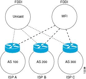
    Incongruent Unicast and Multicast Routes

    12238.jpg


    Illustrates simple unicast and multicast topoligies that are incongruent, and therefore are not possible without multiprotocol BGP.

    Autonomous systems 100, 200, and 300 are each connected to two NAPs that are FDDI rings. One is used for unicast peering (and therefore the exchange of unicast traffic). The Multicast Friendly Interconnect (MFI) ring is used for multicast peering (and therefore the exchange of multicast traffic). Each router is unicast and multicast capable.

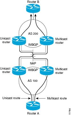
    Multicast BGP Environment

    11754.jpg


    Is a topology of unicast-only routers and multicast-only routers. The two routers on the left are unicast-only routers (that is, they do not support or are not configured to perform multicast routing). The two routers on the right are multicast-only routers. Router A and B support both unicast and multicast routing. The unicast-only and multicast-only routers are connected to a single NAP.

    Only unicast traffic can travel from Router A to the unicast routers to Router B and back. Multicast traffic could not flow on that path, so another routing table is required. Multicast traffic uses the path from Router A to the multicast routers to Router B and back.

    Illustrates a multiprotocol BGP environment with a separate unicast route and multicast route from Router A to Router B. Multiprotocol BGP allows these routes to be incongruent. Both of the autonomous systems must be configured for internal multiprotocol BGP (IMBGP) in the figure.

    A multicast routing protocol, such as PIM, uses the multicast BGP database to perform Reverse Path Forwarding (RPF) lookups for multicast-capable sources. Thus, packets can be sent and accepted on the multicast topology but not on the unicast topology.
  • The 224.192.16.1 multicast IP address maps to 01-00-5E-40-10-01 multicast MAC address.

    Least significant 23 bits of IP address and pre-pend 01-00-5E

    224 ignore
    192 less 128 becomes 64 = 40
    16 = 10
    1 = 01
  • RP/0/RP0/CPU0:router(config)# multicast-routing

    The Cisco IOS-XR configuration command will globally enable PIM and IGMP and MLD multicast processes on the router.

    http://www.cisco.com/c/en/us/td/docs/ios_xr_sw/iosxr_r3-5/multicast/configuration/guide/mc_c35/mc35mcst.html#wp1091637

    Multicast-routing Configuration Submode

    When you issue the multicast-routing ipv4 or multicast-routing ipv6 command, all default multicast components (PIM, IGMP, MLD, MFWD, and MRIB) are automatically started, and the CLI prompt changes to "config-mcast-ipv4" or "config-mcast-ipv6", indicating that you have entered multicast-routing configuration submode.
  • Customer requirements dictate the use of different connectivity types; these are:
    • single-homed connection type
    • dual-attached connection type
    • multihomed connection type
  • Routing that is used between a customer and service provider depends on the selected connectivity type and differs for:
    • single-homed connection type
    • dual-attached connection type
    • multihomed connection type
  • IP addressing and AS numbering depend on the selected connectivity type:
    • single-homed connection type requires IP address scheme
    • dual-attached connection type requires IP address scheme and AS number scheme
    • multihomed connection type requires IP address scheme and AS number scheme
 

PlAwAnSaI

Administrator
  • Static routing can be used with:
    • single-attached customers using single IP address
    • single-attached customers using multiple IP addresses
    • dual-attached customers using a primary and a backup path
    • dual-attached customers using load balancing
  • BGP can be used in dual-attached scenario for conditional advertising on a CE router
  • BGP is used on PE routers by service providers in dual-attached scenarios
  • BGP must remove private AS numbers in dual-attached scenarios
  • BGP is run on both CE and PE in dual-attached scenarios
  • Local AS feature is used to mask the real AS number
  • BGP should be used with:
    • dual-attached customers using a primary and a backup path
    • dual-attached customers using load balancing
    • multihomed customers
    • multihomed customers using a primary and a backup path
    • multihomed customers using load balancing
  • Some service providers allow signalization of BGP services using BGP communities to aid customers using primary and backup paths
  • A customer would like to connect to a service provider. Redundancy and flexibility is requirements should be considered before deciding on a type of connectivity.
  • BGP and static routing is routing options could be used when connecting a customer to a service provider.
  • Dual-attached customer, PA address space, BGP routing, and private AS number and multihomed customer, PI address space, BGP routing, and public AS number is combinations are recommended when connecting a customer to a service provider.
  • Customer networks that can be summarized in a service provider network should be tagged with no-export BGP community when redistributed into BGP.
  • You are a customer connected to a single service provider with two permanent links. You would like to achieve primary and backup traffic distribution. MED for incoming traffic and local preference for outgoing traffic is BGP attributes which you have to manipulate.
  • You are a customer connected to two service providers with one link to each provider. You would like to achieve primary and backup traffic distribution. AS path for incoming traffic and local preference for outgoing traffic is BGP attributes which you have to manipulate.
  • Route propagation focuses on the IP infrastructure layer of the Cisco IP NGN
  • Service providers most commonly use integrated IS-IS and OSPF as interior gateway protocols and BGP as the exterior gateway protocol
  • BGP is used to carry customer routes while IGPs are used to carry service provider internal prefix reachability information
  • BGP allows ISP clients to acquire information about all or some networks reachable through the ISP
  • Static routing or BGP can be used by the ISP to direct traffic going to the customers to the correct links
  • Next-hop-self can be used to avoid redistributing transit segments into IGP on iBGP neighbors
  • When BGP networks grow, various actions must be taken to make them scalable, for iBGP scalability use route reflectors or confederations
  • When IP networks grow, several aspects of addressing need to be considered to reduce sizes of routing tables and to avoid consuming too many addresses
  • BGP accounting feature can be used when an overview of BGP's use of resources or detailed statistical analysis are required
  • BGP reflectors are one of two ways to increase iBGP network scalability
  • iBGP split-horizon rule prevents loops in a fully meshed iBGP cloud
  • A single route reflect is a single point of failure, therefore redundant configuration is essential
  • Route reflectors can be combined into clusters for redundancy
  • Originator-ID BGP attribute is used to prevent routes from being reflected
  • BGP route reflectors allow constructions of flexible network designs
  • BGP route reflectors clusters can be nested many levels deep
  • BGP route reflectors are configured on reflectors only, clients do not know they are clients
  • BGP confederations allow creating AS domains within AS domains
  • BGP intraconfederation interneighbor peering sessions combine the properties of both eBGP and iBGP peering sessions at the same time
  • IS-IS as IGP inside the service provider core network and IBGP between BGP speakers inside the service provider network are routing protocols might be used in a typical service provider network.
  • There is no need to include access links between customers and the service provider in IGP.
  • Private IPv4 addresses on core links and loopback interfaces with MPLS switching, public IPv4 addresses on core links and loopback interfaces, and link-local IPv6 addresses on core links and public IPv6 addresses on loopback interfaces are options can be used to scale IP addressing in service provider networks.
  • Cluster-ID list BGP attribute and originator-ID list BGP attribute are mechanisms used to prevent routing loops in networks with redundant route reflectors.
  • 1. Divide the AS into clusters and designate route reflectors.
    2. Configure a cluster ID on route reflectors.
    3. Configure clients on route reflectors.
    4. On clients, retain only IBGP sessions with route reflectors are the steps that needed to migrate a network to a route reflector - based design into the correct sequence.
  • update-source and ebgp-multihop are Cisco IOS XR Software commands needed to establish an intraconfederation EBGP session between loopback interfaces.
  • When implementing interdomain multicast routing, MSDP is mechanism can be

    used to advertise multicast sources in one domain to the other domains,

    allowing the RPs to build interdomain multicast distribution trees.

    Multicast Source Discovery Protocol

    Multicast Source Discovery Protocol (MSDP) is a mechanism to connect multiple PIM sparse-mode domains. MSDP allows multicast sources for a group to be known to all rendezvous point(s) (RPs) in different domains. Each PIM-SM domain uses its own RPs and need not depend on RPs in other domains.

    An RP in a PIM-SM domain has MSDP peering relationships with MSDP - enabled routers in other domains. Each peering relationship occurs over a TCP connection, which is maintained by the underlying routing system.

    MSDP speakers exchange messages called Source Active (SA) messages. When an RP learns about a local active source, typically through a PIM register message, the MSDP process encapsulates the register in an SA message and forwards the information to its peers. The message contains the source and group information for the multicast flow, as well as any encapsulated data. If a neighboring RP has local joiners for the multicast group, the RP installs the S, G route, forwards the encapsulated data contained in the SA message, and sends PIM joins back towards the source. This process describes how a multicast path can be built between domains.
 

PlAwAnSaI

Administrator
  • Auto RP operations and implementations:

    Candidate RPs send RP announcements to the 224.0.1.39 multicast group,

    and the mapping agents send RP discovery messages to the 224.0.1.40

    multicast group

    Administrative scoping can be configured to limit the scope of the RP announcements

    Auto-RP

    Automatic

    route processing (Auto-RP) is a feature that automates the distribution

    of group-to-RP mappings in a PIM network. This feature has thest

    benefits:
    • It is easy to use multiple RPs within a network to serve different group ranges.
    • It allows load splitting among different RPs.
    • It facilitates the arrangement of RPs according to the location of group participants.
    • It avoids inconsistent, manual RP configurations that might cause connectivity problems.
Multiple

RPs can be used to serve different group ranges or to serve as hot

backups for each other. To ensure that Auto-RP functions, configure

routers as candidate RPs so that they can announce their interest in operating as an RP for certain group ranges.

Additionally,

a router must be designated as an RP-mapping agent that receives the

RP-announcement messages from the candidate RPs, and arbitrates

conflicts. The RP-mapping agent sends the consistent group-to-RP

mappings to all remaining routers. Thus, all routers automatically

determine which RP to use for the groups they support.

auto-rp candidate-rp

To

configure a router as a Protocol Independent Multicast (PIM) rendezvous

point (RP) candidate that sends messages to the well-known

CISCO-RP-ANNOUNCE multicast group (224.0.1.39), use the auto-rp candidate-rp command in PIM configuratiion mode. To return to the default behavior, use the no form of this command.

auto-rp candidate-rp
type interface-path-id scope ttl-value [group-list access-list-name] [interval seconds]
no auto-rp candidate-rp
type interface-path-id scope ttl-value [group-list access-list-name] [interval seconds]

  • Cisco IP NGN Infrastructure Layer
    • BGP security and optimization options are used in the core and IP edge portions of the service provider network.
    • Some options are used on the customer edge devices, as well.
  • Threats in Service Provider Environments
    • Threats to the BGP of the service provider:
      • BGP relies on TCP as its transport protocol.
      • BGP is susceptible to the same attacks that apply to any TCP-based protocol (DoS attacks).
      • BGP is the most frequently targeted routing protocol, since it is used across the Internet.
      • Service providers should take extreme caution to mitigate risks of exploiting BGP routing protocol.
      • Inadvertent mistakes during BGP configuration can be serious and can have worldwide consequences.
    • Attacks can be performed against a customer, usually using a form of DDoS:
      • Such attacks can cause collateral damage to the infrastructure of the service provider, due to large amounts of traffic.
      • Countermeasures should be taken to prevent damage to the service provider.
  • BGP Threats Summary
    • BGP routing table manipulation:
      • An attacker is able to alter the content of the BGP table.
    • BGP route spoofing:
      • An attacker announces the prefix of the (spoofed) victim to reroute traffic for the victim to itself.
    • BGP DoS:
      • An attacker sends large amount of unexpected BGP traffic to the BGP router to expend hardware resources (CPU, memory).
  • BGP Countermeasures Overview
    • BGP Neighbor Authentication: BGP Table Manipulation
    • BGP TTL Security Check: BGP Table Manipulation and BGP DoS
    • BGP Maximum Prefix: BGP DoS
    • CoPP: BGP Table Manipulation and BGP DoS
    BGP route spoofing can be prevented using filtering based on prefixes and AS path.
  • BGP Route Limiting
    • All filtering mechanisms specify only what you are willing to accept but not how much.
    • A misconfigured BGP neighbor can send a huge number of prefixes, which can exhaust the memory of a router or overload the CPU (several Internet-wide incidents have already occurred).
    • BGP maximum prefixes limiting is used to establish a hard limit on the number of prefixes received from a neighbor.
    • It is enabled by default on Cisco IOS XR Software to impose limitations for different address families.
    • BGP router terminates peering when a number of maximum prefixes is exceeded.
    • A router can be configured to:
      • Generate a logging message when a specified percentage of the maximum prefixes is reached
      • Reestablish BGP peering after a specified time
      • Generate a logging message when the maximum prefix limit is exceeded, instead of terminating BGP peering
  • Configuration
    • IOS:
      router bgp 123
      neighbor 209.165.201.130 remote-as 234
      neighbor 209.165.201.130 maximum-prefix 10 70 restart 5 ! Enable BGP route limiting for IPv4
      !
      neighbor 2001:db8:128::130 remote-as 234
      address family ipv6 unicast
      neighbor 2001:db8:128::130 activate
      neighbor 2001:db8:128::130 maximum-prefix 10 70 restart 5 ! Enable BGP route limiting for IPv6
    • IOS XR:
      router bgp 123
      neighbor 209.165.201.134
      remote-as 345
      address-family ipv4 unicast
      maximum-prefix 100000 80 restart 5 ! Enable BGP route limiting for IPv4
      !
      neighbor 2001:db8:132::134
      remote-as 345
      address-family ipv6 unicast
      maximum-prefix 10000 80 restart 5 ! Enable BGP route limiting for IPv6
  • Verification
    • Displays BGP neighbor information

      RP/0/RSP0/CPU0:pE2#show bgp neighbor 209.165.201.134
      BGP neighbor is 209.165.201.134
      Remote AS 345, local AS 123, external link

      Maximum prefixes allowed 100000
      Threshold for warning message 80%, restart interval 5 min
    • Logging messages displayed when limit is exceeded

      RP/0/RSP0/CPU0:Oct 11 13:31:23.697 : bgp[1048] : %ROUTING-BGP-4-MAXPFXEXCEED : No. of IPv4 Unicast prefixes received from 209.165.201.134 : 100001 exceed limit 100000
      RP/0/RSP0/CPU0:Oct 11 13:31:23.697 : bgp[1048] : %ROUTING-BGP-5-ADJCHANGE : neighbor 209.165.201.134 Down - Peer exceeding maximum prefix limit (CEASE notification sent - maximum number of prefixes reached) (VRF: default)
  • BGP Neighbor Authentication
    • BGP neighbors can be authenticated before establishing a TCP session:
      • HMAC-MD5 is used.
      • Cisco IOS XR supports HMAC-SHA1 with key chains.
    • To calculate a hash, part of an IP and an entire TCP header with data is used together with a pre-shared key.
    • Every TCP segment is authenticated and the hash is prepended as TCP option 19.
    • The hash is calculated on the receiving BGP router and compared with the received hash.
  • BGP TTL Security Check
    • Takes into account that valid EBGP sessions are established between connected interfaces or loopback interfaces
    • Enforces that received TTL should match a specified value
    • Can prevent DoS attack from non-directly connected neighbors by setting the received TTL to 254 or 253
    • When enabled, sets TTL of outgoing BGP packets to 255
 

PlAwAnSaI

Administrator
  • Control Plane Policing
    • CoPP (Cisco IOS and IOS XE Software only) can be used to control traffic to the control plane of a router:
      • Permits, denies, and rate limits access to the control plane
      • Configured as service policy, applied to virtual control plane interface
      • Can be used to filter and rate-limit BGP traffic to the router
    • LPTS (Cisco IOS XR Software):
      • LPTS policers are responsible for policing traffic to the RPs on the incoming line cards.
      • Policer values can be changed for each line card separately.
      • They can be used to rate-limit BGP traffic to the router.
  • Configuration
    • IOS:
      router bgp 123
      neighbor 209.165.201.129 password C!sc() ! Enable neighbor authentication
      neighbor 209.165.201.129 ttl-security hops 1 ! Enable TTL security
      !
      ip access-list extended BGP
      permit tcp host 209.165.201.129 host 209.165.201.130 eq bgp
      permit tcp host 209.165.201.129 eq bgp host 209.165.201.130
      deny ip any any
      !
      class-map BGP_CLASS
      match access-group name BGP
      !
      policy-map COPP_POLICY
      class BGP_CLASS
      police rate 200 pps conform-action transmit exceed-action drop
      ! Configure CoPP
      control-plane
      service-policy input COPP_POLICY
    • IOS XR:
      router bgp 123
      neighbor 209.165.201.130
      password C!sc() ! Enable neighbor authentication
      ttl-security ! Enable TTL security
      ! Configure LPTS
      lpts pifib hardware police
      flow bgp configured rate 200 ! Default Packet Rate 2000
      flow bgp default rate 200 ! Default Rate 2500
      flow bgp known rate 200 ! Default 1500
  • Remote-Triggered Black-Hole Filtering
    • When a customer is under DDoS attack, the vast amount of traffic can also cause collateral damage to the infrastructure of the service provider.
    • Once the attack has been detected, traffic related to the DDoS should be discarded on the edge of service provider network.
    • One BGP router should be designated as signaling router:
      • The router signals over BGP to the edge routers that traffic causing DoS should be discarded.
    • Destination-based RTBH:
      • Traffic going to the IP addresses of the customer is discarded on the edge.
    • Source-based RTBH:
      • Traffic coming from the IP addresses of the attacker is discarded on the edge.
      • Uses strict uRPF with BGP signaling.
  • Destination-Based RTBH
    • All the routers:
      router static
      address-family ipv4 unicast
      192.0.2.0/24 null0
    • Signaling router:
      !When attack has been detected:
      router static
      address-family ipv4 unicast
      209.165.201.128/28 null0 tag 666
    • Signaling router:
      router static
      address-family ipv4 unicast
      192.0.2.0/24 Null0
      !
      route-policy RTBH
      if tag is 666 then
      set next-hop 192.0.2.1
      set community (no-export)
      set local-preference 1000
      endif
      end-policy
      !
      router bgp 123
      address-family ipv4 unicast
      redistribute static route-policy RTBH
  • Verification
    • Displays BGP table

      RP/0/RSP0/CPU0:pE1# show bgp
      Status codes: s suppressed, d damped, h history, * valid, > best
      i - internal, r RIB-failure, S stale
      Origin codes: i - IGP, e - EGP, ? - imcomplete
      Network Next Hop Metric LocPrf Weight Path
      *>i209.165.201.128/28 192.0.2.1 0 1000 0 I

    • Pings the target

      RP/0/RSP0/CPU0:pE1# ping 209.165.201.129
      Fri Sep 30 13:37:41.482 UTC
      Type escape sequence to abort.
      Sending 5, 100-byte ICMP Echos to 209.165.201.129, timeout is 2 seconds:
      UUUUU
      Success rate is 0 percent (0/5)

  • Which RP to use from a set of candidate RPs in the RP set is determined by running the same hash algorithm on all PIMv2 routers.

    bsr candidate-bsr

    To configure the router to announce its candidancy as a bootstrap router (BSR), use the bsr candidate-bsr command in router pim configuration mode. To return to the default behavior, use the no form of this command.

    bsr candidate-bsr ip-address [hash-mask-len length] [priority value]
    no bsr candidate-bsr ip-address [hash-mask-len length] [priority value]

    ip-address = IP address of the BSR router for the domain. For IPv4, this is an IP address in four-part dotted-decimal notation. For IPv6, the IP address is specified in hexadecimal format using 16-bit values between colons.

    hash-mask-len length = (Optional) Length of a mask that is to be used in the hash function.
    • All groups with the same seed hash (correspond) to the same RP. For example, if this value is 24, only the first 24 bits of the group addresses matter. This fact allows you to get one RP for multiple groups.
    • For IPv4 addresses, a value of 30 is recommended. The range is 0 to 32.
    • For IPv6 addresses, a value of 126 is recommended. The range is 0 to 128.
    priority value = (Optional) Priority of the candidate BSR. Range is 1 to 255. The BSR with the higher priority is recommended. If the priority values are the same, the router with the higher IP address is the BSR.
  • When configuring PIM operations, the last-hop routers will never switch over to the shortest path tree and will always remain on the shared tree is the effect of setting the SPT threshold to infinity.
  • 232.0.0.0/8 is multicast group range reserved for SSM.

    PIM-SSM Operations

    PIM in Source Specific Multicast operation uses information found on source addresses for a multicast group provided by receivers and performs source filtering on traffic.
    • By default, PIM-SSM operates in the 232.0.0.0/8 multicast group range for IPv4 and ff3x::/32 (where x is any valid scope) in IPv6. To configure these values, use the ssm range command.
    • If SSM is deployed in a network already configured for PIM-SM, only the last-hop routers must be upgraded with Cisco IOS XR software that supports the SSM feature.
    • No MSDP SA messages within the SSM range are accepted, generated, or forwarded.
 

PlAwAnSaI

Administrator
  • MSDP configurations and operations:

    The MSDP peers are also typically the RPs in respective routing domains.

    MSDP establishes neighbor relationships with other MSDP peers using TCP port 639.

    On Cisco IOS, IOS-XE, and IOS-XR, the router can be configured to cache the SA messages to reduce the join latency.

    SA messages are used to advertise active sources in a domain.

    http://www.cisco.com/en/US/docs/ios/ipmulti/configuration/guide/imc_msdp_im_pim_sm.html

    When

    MSDP is enabled, an RP in a PIM-SM domain maintains MSDP peering

    relationships with MSDP-enabled routers in other domains. This peering

    relationship occurs over a TCP connection, where primarily a list of

    sources sending to multicast groups is exchanged. MSDP uses TCP (port

    639) for its peering connections. As with BGP, using point-to-point TCP

    peering means that each peer must be explicitly configured. The TCP

    connections between RPs, moreover, are achieved by the underlying

    routing system. The receiving RP uses the source lists to establish a

    source path. If the multicast sources are of interest to a domain that

    has receivers, multicast data is delivered over the normal, source-tree

    building mechanism provided by PIM-SM. MSDP is also used to announce

    sources sending to a group. These announcements must originate at the RP

    of the domain.
  • When verifying multicast configurations and operations on Cisco IOS-XR

    routers:

    Use the show pim rpf command to display the RPF information for the RP or for the multicast source.

    show pim rpf

    To display information about reverse-path forwarding (RPF) in one or more routing tables within Protocol Independent Multicast (PIM), use the show pim rpf command in EXEC mode.

    show pim [vrf vrf-name] [ipv4 | ipv6] {multicast | safi-all | unicast} [topology{tablename | all}] rpf [ip-address / name]

    vrf vrf-name = (Optional) Specifies a VPN routing and forwarding (VRF) instance.

    ipv4 = (Optional) Specifies IPv4 address prefixes.

    ipv6 = (Optional) Specifies IPv6 address prefixes.

    multicast = (Optional) Specifies a multicast secondary address family (SAFI).

    safi-all = (Optional) Specifies a secondary address family (SAFI) wildcard.

    unicast = (Optional) Specifies a unicast secondary address family (SAFI).

    topology = (Optional) Specifies the display of multitopology routing table information.

    table-name = Name of the specific multitopology table to show.

    all = Specifies that detailed information be displayed for all multitopology routing tables in PIM.

    ip-address / name = (Optional) IP address or name, or both, for the default or selected route policy:
    • IP address as defined in the Domain Name System (DNS) hosts table or with the domain IPv4 host in the format A.B.C.D.
    • IP address as defined in the Domain Name System (DNS) hosts table or with the domain IPv6 host in the form of X:X::X.
    Note The ip-address argument can also be a Protocol Independent Multicast (PIM) rendezvous point (RP) address.

    Use the show mfib route command to display the (*,G) and (S,G) states information on the router.

    show mfib route

    To display route entries in the Multicast Forwarding Information Base (MFIB) table, use the show mfib route command in EXEC mode.

    show mfib [vrf vrf-name] [ipv4 | ipv6] route [rate | statistics | * | source-IP-address | group-IP-address /prefix-length | detail | old-output | summary | location node-id]

    vrf vrf-name = (Optional) Specifies a VPN routing and forwarding (VRF) instance.

    ipv4 = (Optional) Specifies IPv4 address prefixes.

    ipv6 = (Optional) Specifies IPv6 address prefixes.

    rate = (Optional) Displays individual (S, G) rates.

    statistics = (Optional) Displays both hardware and software forwarding statistics.

    * = (Optional) Displays shared tree entries.

    source-IP-address = (Optional) IP address or hostname of the multicast route source. Format is A.B.C.D or X:X::X.

    group-IP-address = (Optional) IP address or hostname of the multicast group. Format is A.B.C.D or X:X::X.

    /prefix-length = (Optional) Group IP prefix length of the multicast group. A decimal value that indicates how many of the high-order contiguous bits of the address compose the prefix (the network portion of the address). Format is: A.B.C.D/length or X:X::X/length. A slash must precede the decimal value.

    detail = (Optional) Specifies detailed route information.

    old-output = (Optional) Displays the old show output - available for backward compatibility.

    summary = (Optional) Displays a brief list of the routing database.

    location node-id = (Optional) Specifies an MFIB designated node. The node-id argument is entered in the rack/slot/module notation.
  • Assume that the R1 router is enabled for PIM-SM and receives a multicast

    packet sourced from 172.16.1.100, and the R1 router has multicast

    receivers on the Gi0/1, Gi0/2, Gi0/3 and Gi0/4 interfaces.

    R1 routing table:

    172.16.1.0/24 via Gi0/1
    172.16.2.0/24 via Gi0/2
    172.16.3.0/24 via Gi0/3
    0.0.0.0/0 via Gi0/4

    The multicast

    packet from the 172.16.1.100 source must arrive on Gi0/1 interface on

    the R1 router for it to be forwarded out the other interfaces.
 

PlAwAnSaI

Administrator
  • Refer to the exhibit.

    router bgp 65123
    bgp graceful-restart

    This command is used to enable NSF and is entered on the NSF-capable router, and also on any NSF-aware peer.

    Graceful

    restart is supported in recent versions of Cisco IOS software (12.0S)

    and is supported in Cisco IOS XR software. Graceful restart is the

    mechanism by which BGP routing peers avoid changes to their forwarding

    paths following a switchover. If the BGP peer has received this

    capability, it is aware that the device sending the message is nonstop

    forwarding (NSF)-capable. Both the NSF-capable router and its BGP peers

    (NSF-aware peers) need to exchange the graceful restart capability in

    their OPEN messages, at the time of session establishment. If both peers

    do not exchange the graceful restart capability, the session will not

    be graceful restart-capable.

    If the BGP session is lost during a

    Route Processor (RP) switchover or BGP process restart, the NSF-aware

    BGP peer marks all the routes associated with the NSF-capable router as

    stale; however, it continues to use these routes to make forwarding

    decisions for a set period of time. This functionality means that no

    packets are lost while the newly active RP is waiting for convergence of

    the routing information with its BGP peers.

    After a failover

    event occurs, the NSF-capable router reestablishes the session with the

    BGP peer. In establishing the new session, it sends a new graceful

    restart message that identifies the NSF-capable router as having

    restarted.

    At this point, the routing information is exchanged

    between the two BGP peers. Once this exchange is complete, the

    NSF-capable device uses the newly received routing information to update

    the RIB and the Forwarding Information Base (FIB) with the new

    forwarding information. The NSF-aware device uses the network

    information to remove stale routes from its BGP table. The BGP protocol

    is then fully converged.

    If a BGP peer does not support the

    graceful restart capability, it will ignore the graceful restart

    capability in an OPEN message but will establish a BGP session with the

    NSF-capable device. This functionality will allow interoperability with

    non-NSF-aware BGP peers (and without NSF functionality), but the BGP

    session with non-NSF-aware BGP peers will not be graceful

    restart-capable.
  • Refer to the exhibit.

    router bgp 64500
    bfd multiplier 2
    bfd minimum-interval 20
    address-family ipv4 unicast
    network 10.1.1.0/24
    !
    address-family ipv6 unicast
    !
    neighbor 192.168.1.1
    remote-as 65001
    address-family ipv4 unicast
    !
    end

    Configuration is missing to complete the

    configuration task of enabling BFD with the 192.168.1.1 EBGP peer:

    bfd fast-detect also needs to be enabled for the

    192.168.1.1 neighbor under neighbor 192.168.1.1

    RP/0/RSP0/CPU0:p1(config-bgp-nbr)#bfd fast-detect

    bfd fast-detect

    To enable bidirectional forwarding detection (BFD) to detect failures in the path between adjacent forwarding engines, use the bfd fast-detect command in the appropriate configuration mode. To return the software to the default state in which BFD is not enabled, use the no form of this command.

    bfd fast-detect [disable | ipv4]
    no bfd fast-detect

    disable = Prevents BFD settings from being inherited from the parent.

    ipv4 = Enables Intermediate System-to-Intermediate System (IS-IS) BFD detection of failures in the path between adjacent forwarding engines.
    Note The ipv4 keyword is available in IS-IS router configuration mode only.

    Defaults
    BFD is not enabled.

    Command Modes

    BGP configuration mode
    Neighbor configuration
    Session group configuration
    Neighbor group configuration

    IS-IS router configuration mode
    Interface configuration

    MPLS-TE configuration mode
    Interface configuration

    OSPF router configuration mode
    Router configuration
    Area configuration
    Area Interface configuration
  • PIM triggered join and NSF/SSO features are used to provide high availability multicast.

    Triggered joins are sent when the primary or the secondary RPF information changes. No RPF change prunes are sent for MoFRR streams.

    mofrr

    To perform a fast convergence (multicast-only fast reroute, or MoFRR) of specified routes/flows when a failure is detected on one of multiple equal-cost paths between the router and the source, use the mofrr command under PIM configuration mode.

    mofrr rib acl_name
    no rib acl_name
  • On Cisco IOS-XR, neighbor-group is BGP configuration group allows to define

    address-family independent commands and address-family dependent

    commands for each address family.

    Commands relating to a peer group found in Cisco IOS Release 12.2 have been removed from Cisco IOS XR software. Instead, the af-group, session-group, and neighbor-group configuration commands are added to support the neighbor in Cisco IOS XR software:
    • The af-group command is used to group address family-specific neighbor commands within an IPv4 or IPv6 address family. Neighbors that have the same address family configuration are able to use the address family group name for their address family-specific configuration. A neighbor inherits the configuration from an address family group by way of the use command. If a neighbor is configured to use an address family group, the neighbor will (by default) inherit the entire configuration from the address family group. However, a neighbor will not inherit all of the configuration from the address family group if items are explicitly configured for the neighbor.
    • The session-group command allows to create a session group from which neighbors can inherit address family-independent configuration. A neighbor inherits the configuration from a session group by way of the use command. If a neighbor is configured to use a session group, the neighbor (by default) inherits the session group's entire configuration. A neighbor does not inherit all the configuration from a session group if a configuration is done directly on that neighbor.
    • The neighbor-group command helps apply the same configuration to one or more neighbors. Neighbor groups can include session groups and address family groups. This additional flexibility can create a complete configuration for a neighbor. Once a neighbor group is configured, each neighbor can inherit the configuration through the use command. If a neighbor is configured to use a neighbor group, the neighbor (by default) inherits the neighbor group's entire BGP configuration.
    • However, a neighbor will not inherit all of the configuration from the neighbor group if items are explicitly configured for the neighbor. In addition, some part of the neighbor group's configuration could be hidden if a session group or address family group was also being used.
 

PlAwAnSaI

Administrator
  • Refer to the Cisco IOS-XR configuration exhibit.

    multicast-routing
    !
    interface Loopback0
    ipv4 address 10.3.1.1 255.255.255.255
    !
    interface GigabitEthernet0/0/0/0
    ipv4 address 192.168.103.30 255.255.255.0
    no shut
    !
    interface GigabitEthernet0/0/0/1
    ipv4 address 192.168.156.50 255.255.255.0
    no shut
    !
    router isis 1
    net 49.0005.0100.0300.1001.00
    address-family ipv4 unicast
    !
    interface Loopback0
    address-family ipv4 unicast
    !
    interface GigabitEthernet0/0/0/0
    address-family ipv4 unicast
    !
    interface GigabitEthernet0/0/0/1
    address-family ipv4 unicast
    !
    router pim
    address-family ipv4
    auto-rp mapping-agent Loopback0 scope 16
    auto-rp candidate-rp Loopback0 scope 16
    !
    interface Loopback0
    enable
    !
    interface GigabitEthernet0/0/0/0
    enable
    !
    interface GigabitEthernet0/0/0/1
    enable
    !

    The Cisco IOS-XR router

    is unable to establish any PIM neighbor relationships. The configuration is missing:
    multicast-routing
    address-family ipv4
    interface gi0/0/0/0
    enable
    interface gi0/0/0/1
    enable
  • The show ip bgp commands is used to display the contents of the BGP routing table. The output can be filtered to display entries for a specific prefix, prefix length, and prefixes injected through a prefix list, route map, or conditional advertisement.

    Router# show ip bgp

    BGP table version is 22, local router ID is 10.1.1.1
    Status codes: s suppressed, d damped, h history, * valid, > best, i - internal,
    r RIB-failure, S Stale, m multipath, b backup-path, x best-external
    Origin codes: i - IGP, e - EGP, ? - incomplete

    Network Next Hop Metric LocPrf Weight Path
    *> 10.1.1.1/32 0.0.0.0 0 32768 i
    *>i10.2.2.2/32 172.16.1.2 0 100 0 i
    *bi10.9.9.9/32 192.168.3.2 0 100 0 10 10 i
    *> 192.168.1.2 0 10 10 i
    * i172.16.1.0/24 172.16.1.2 0 100 0 i
    *> 0.0.0.0 0 32768 i
    *> 192.168.1.0 0.0.0.0 0 32768 i
    *>i192.168.3.0 172.16.1.2 0 100 0 i
    *bi192.168.9.0 192.168.3.2 0 100 0 10 10 i
    *> 192.168.1.2 0 10 10 i
    *bi192.168.13.0 192.168.3.2 0 100 0 10 10 i
    *> 192.168.1.2 0 10 10 i

    BGP table version = Internal version number of the table. This number is incremented whenever the table changes.

    local router ID = IP address of the router.

    Status codes = Status of the table entry. The status is displayed at the beginning of each line in the table. It can be one of the following values:
    • s - The table entry is suppressed.
    • d - The table entry is dampened.
    • h - The table entry history.
    • * - The table entry is valid.
    • > - The table entry is the best entry to use for that network.
    • i - The table entry was learned via an internal BGP (iBGP) session.
    • r - The table entry is a RIB-failure.
    • S - The table entry is stale.
    • m - The table entry has multipath to use for that network.
    • b - The table entry has backup path to use for that network.
    • x - The table entry has best external route to use for the network.
    Origin codes = Origin of the entry. The origin code is placed at the end of each line in the table. It can be one of the following values:
    • i - Entry originated from an Interior Gateway Protocol (IGP) and was advertised with a network router configuration command.
    • e - Entry originated from an Exterior Gateway Protocol (EGP).
    • ? - Origin of the path is not clear. Usually, this is a router that is redistributed into BGP from an IGP.
    Network = IP address of a network entity.

    Next Hop = IP address of the next system that is used when forwarding a packet to the destination network. An entry of 0.0.0.0 indicates that the router has some non-BGP routes to this network.

    Metric = If shown, the value of the interautonomous system metric.

    LocPrf = Local preference value as set with the set local-preference route-map configuration command. The default value is 100.

    Weight = Weight of the route as set via autonomous system filters.

    Path = Autonomous system paths to the destination network. There can be one entry in this field for each autonomous system in the path.

    (stale) = Indicates that the following path for the specified autonomous system is marked as "stale" during a graceful restart process.
  • Use the show ip bgp neighbors command to display BGP and TCP connection information for neighbor sessions. For BGP, this includes detailed neighbor attribute, capability, path, and prefix information. For TCP, this includes statistics related to BGP neighbor session establishment and maintenance.

    Prefix activity is displayed based on the number of prefixes that are advertised and withdrawn. Policy denials display the number of routes that were advertised but then ignored based on the function or attribute that is displayed in the output.
 

PlAwAnSaI

Administrator
  • Router# show ip bgp neighbors 10.108.50.2

    BGP neighbor is 10.108.50.2, remote AS 1, internal link
    BGP version 4, remote router ID 192.168.252.252
    BGP state = Established, up for 00:24:25
    Last read 00:00:24, last write 00:00:24, hold time is 180, keepalive interval is
    60 seconds
    Neighbor capabilities:
    Route refresh: advertised and received(old & new)
    MPLS Label capability: advertised and received
    Graceful Restart Capability: advertised
    Address family IPv4 Unicast: advertised and received
    Message statistics:
    InQ depth is 0
    OutQ depth is 0
    Sent Rcvd
    Opens: 3 3
    Notifications: 0 0
    Updates: 0 0
    Keepalives: 113 112
    Route Refresh: 0 0
    Total: 116 115
    Default minimum time between advertisement runs is 5 seconds

    For address family: IPv4 Unicast
    BGP additional-paths computation is enabled
    BGP advertise-best-external is enabled
    BGP table version 1, neighbor version 1/0
    Output queue size : 0
    Index 1, Offset 0, Mask 0x2
    1 update-group member
    Sent Rcvd
    Prefix activity: ---- ----
    Prefixes Current: 0 0
    Prefixes Total: 0 0
    Implicit Withdraw: 0 0
    Explicit Withdraw: 0 0
    Used as bestpath: n/a 0
    Used as multipath: n/a 0

    Outbound Inbound
    Local Policy Denied Prefixes:


    Total: 0 0
    Number of NLRIs in the update sent: max 0, min 0

    Connections established 3; dropped 2
    Last reset 00:24:26, due to Peer closed the session
    External BGP neighbor may be up to 2 hops away.
    Connection state is ESTAB, I/O status: 1, unread input bytes: 0
    Connection is ECN Disabled
    Local host: 10.108.50.1, Local port: 179
    Foreign host: 10.108.50.2, Foreign port: 42698

    Enqueued packets for retransmit: 0, input: 0 mis-ordered: 0 (0 bytes)

    Event Timers (current time is 0x68B944):
    Timer Starts Wakeups Next
    Retrans 27 0 0x0
    TimeWait 0 0 0x0
    AckHold 27 18 0x0
    SendWnd 0 0 0x0
    KeepAlive 0 0 0x0
    GiveUp 0 0 0x0
    PmtuAger 0 0 0x0
    DeadWait 0 0 0x0

    iss: 3915509457 snduna: 3915510016 sndnxt: 3915510016 sndwnd: 15826
    irs: 233567076 rcvnxt: 233567616 rcvwnd: 15845 delrcvwnd: 539

    SRTT: 292 ms, RTTO: 359 ms, RTV: 67 ms, KRTT: 0 ms
    minRTT: 12 ms, maxRTT: 300 ms, ACK hold: 200 ms
    Flags: passive open, nagle, gen tcbs
    IP Precedence value : 6

    Datagrams (max data segment is 1460 bytes):
    Rcvd: 38 (out of order: 0), with data: 27, total data bytes: 539
    Sent: 45 (retransmit: 0, fastretransmit: 0, partialack: 0, Second Congestion: 08

    BGP neighbor = IP address of the BGP neighbor and its autonomous system number.

    remote AS = Autonomous system number of the neighbor.

    local AS 300 no-prepend (not shown in display) = Verifies that the local autonomous system number is not prepended to received external routes. This output supports the hiding of the local autonomous systems when migrating autonomous systems.
 

PlAwAnSaI

Administrator
  • Referring to the topology diagram show in the exhibit:

    image.php


    The IBGP routing updates received by R3 from R2 will be propagated to the R6 router.

    The EBGP routing updates received by R1 from R5 will be propagated to the R2, R4, and R7 routers.

    The EBGP routing updates received by R3 from R6 will be propagated to the R2 and R4 routers.
  • When a BGP route reflector receives an IBGP update from a non-client

    IBGP peer, the route reflector will then forward the IBGP updates to the EBGP peers and other clients only.
  • Use the show ip mroute command to display information about mroute entries in the mroute table. The Cisco IOS software populates the multicast routing table by creating (S, G) entries from (*, G) entries. The asterisk (*) refers to all source addresses, the "S" refers to a single source address, and the "G" is the destination multicast group address. In creating (S, G) entries, the software uses the best path to that destination group found in the unicast routing table (that is, through Reverse Path Forwarding [RPF]).

    Use the clear ip mroute command to delete entries from the mroute table.

    Examples

    The following is sample output from the show ip mroute command for a router operating in sparse mode:

    Router# show ip mroute

    IP Multicast Routing Table
    Flags: D - Dense, S - Sparse, C - Connected, L - Local, P - Pruned
    R - RP-bit set, F - Register flag, T - SPT-bit set
    Timers: Uptime/Expires
    Interface state: Interface, Next-Hop, State/Mode

    (*, 224.0.255.3), uptime 5:29:15, RP is 198.92.37.2, flags: SC
    Incoming interface: Tunnel0, RPF neighbor 10.3.35.1, Dvmrp
    Outgoing interface list:
    Ethernet0, Forward/Sparse, 5:29:15/0:02:57

    (198.92.46.0/24, 224.0.255.3), uptime 5:29:15, expires 0:02:59, flags: C
    Incoming interface: Tunnel0, RPF neighbor 10.3.35.1
    Outgoing interface list:
    Ethernet0, Forward/Sparse, 5:29:15/0:02:57

    Flags: = Provides information about the entry.

    D - Dense = Entry is operating in dense mode.

    S - Sparse = Entry is operating in sparse mode.

    C - Connected = A member of the multicast group is present on the directly connected interface.

    L - Local = The router itself is a member of the multicast group.

    P - Pruned = Route has been pruned. The Cisco IOS software keeps this information in case a downstream member wants to join the source.

    R - RP-bit set = Indicates that the (S, G) entry is pointing toward the rendezvous point (RP). The RP is typically a prune state along the shared tree for a particular source.
  • Introducing BGP Confederations:

    http://cisco.com/web/learning/le31/le46/cln/qlm/CCIP/bgp/introducing-bgp-confederations-2/player.html
  • Introducing Route Reflectors:

    http://www.cisco.com/web/learning/le31/le46/cln/qlm/CCIP/bgp/introducing-route-reflectors-2/player.html
  • Understanding BGP Path Attributes:
    http://www.cisco.com/web/learning/le31/le46/cln/qlm/CCIP/bgp/understanding-bgp-path-attributes-3/player.html
 
Top